background image

Install Ground Pad or Wall Hangers

1.  Determine proper location for outdoor unit.
2.  Follow all instructions provided by manufacturer for installing wall hangers or ground pad.
3.  Verify the wall hangers or ground pad can safely support the weight of the outdoor unit.
4.  Verify the wall hangers or ground pad is level and meets all outdoor dimensional clearances.

Install Outdoor Unit Risers

If the outdoor unit requires added elevation above the ground, installing riser legs will provide
a sturdy and stable solution.  Follow all instructions provided by manufacturer for installing 
riser legs to outdoor unit.

NOTE:

Riser legs will also help absorb vibrations and noise while facilitating proper drainage.

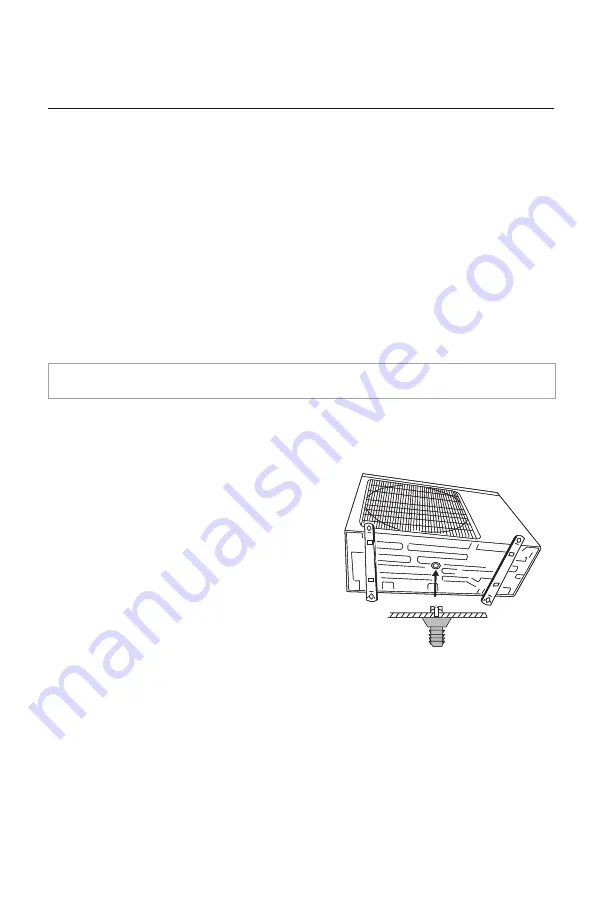
Install Condensate Drain for Outdoor Unit

During normal heating and defrost operation, 
the outdoor unit will generate condensate water.  
The condensate water should be routed to a safe 
location through the drain hose.

1.  Locate drain hole on bottom of outdoor unit.

2.  Install the outdoor drain fitting into hole on

the bottom of outdoor unit as shown.

3.  Connect the drain hose to drain fitting.

4.  Route drain hose to safe location for proper 

drainage of excess condensate water.

5.  Plug the remaining drain holes in basepan with 

plugs provided from factory.

OUTDOOR UNIT INSTALLATION 

Drain Fitting Installation

18

Summary of Contents for Multi21 Series

Page 1: ...Models MULTI18HP230V1BO MULTI24HP230V1BO MULTI30HP230V1BO MULTI36HP230V1BO MULTI42HP230V1BO DUCTLESS INVERTER HEAT PUMP INSTALLATION MANUAL ...

Page 2: ...stallation Mounting Bracket and Refrigerant Piping 19 20 Piping Installation 21 26 Power andWiring Installation 27 31 Testing and Inspection 32 33 Start Up 34 Troubleshooting 35 36 Diagnostic Codes 37 40 AppendixA 41 Warranty Back Thank you for choosing a Ductless Heat Pump for your customer Please read this installation manual carefully before installing and starting up the Multi21 System Take a ...

Page 3: ...anual 2 Installation must be performed in accordance with local laws regulations and National Electrical Codes NEC 3 If refrigerant leaks while work is being carried out ventilate the area Do not allow refrigerant to come in contact with a flame as it produces toxic gas 4 Disconnect all electrical power to the indoor and outdoor units until the system is ready for start up and checkout 5 When inst...

Page 4: ...Outdoor Unit NOMENCLATURE 3 ...

Page 5: ...t D 1 4 6 3 8 9 5 Port E 1 4 6 3 8 9 5 Unit Size Max Total Pipe Min Equivalent Max Equivalent Max Elev btwn Max Elev btwn BtuH Length ft m Pipe Length ft m PipeLength ft m IND Units ft m IND OTDUnitsft m 18 000 65 20 10 3 33 10 33 10 33 10 24 000 197 60 10 3 65 20 33 10 33 10 30 000 230 70 10 3 82 25 25 7 5 49 15 36 000 246 75 10 3 82 25 25 7 5 49 15 42 000 246 75 10 3 82 25 25 7 5 49 15 Unit Size...

Page 6: ...rench Hex Keys orAllenWrenches Drill Drill Bits Hole Saw Pipe Cutter Screw drivers Phillips Flat blade Manifold and Gauges Level R410A FlaringTool Clamp onAmp Meter Vacuum Pump Safety Glasses Work Gloves Refrigerant Scale Micron Gauge SUGGESTEDTOOLS 5 ...

Page 7: ...ructure i e wall ceiling floor strong enough to withstand four times the full weight and vibration of the unit 7 Filter can be easily accessed for cleaning 8 Leave enough free space to allow access for routine maintenance 9 Install at least 10 ft 3 m away from the antenna ofTV set or radio Operation of the air conditioner may interfere with radio orTV reception in areas where reception is weak An ...

Page 8: ...he condensate water can be drained unobstructed during the heating mode to a safe location 4 Do not locate the unit where the noise may be objectionable to neighbors 5 Provide the space shown below so that the air flow is not blocked and future service and maintenance can be performed Outdoor Unit INSTALLATION SITE INSTRUCTIONS Select a site that allows the following Air inlet Air outlet Minimum O...

Page 9: ...TALLATION Model A B C CROWN09HP230V1A 37 8 960 12 6 320 8 1 205 CROWN12HP230V1A 37 8 960 12 6 320 8 1 205 CROWN18HP230V1A 37 8 960 12 6 320 8 1 205 3 1 2 27 7 3 8 3 1 8 2 INDOOR UNIT DIMENSIONS in mm Crown Unit Mounting Bracket Diagram inches 9K 12K and 18K Unit Crown 8 A C B 3 5 27 0 7 1 3 1 2 0 Left Right Rear piping hole Rear piping hole ...

Page 10: ...1AH 34 1 866 11 5 292 8 2 208 TERRA18HP230V1BH 40 1 1018 12 6 319 9 1 231 TERRA24HP230V1BH 46 4 1178 12 8 325 10 4 264 PIPE SIZE in mm Unit Size BtuH Liquid Line Suction Gas Line 9 000 1 4 6 1 2 12 12 000 1 4 6 1 2 12 18 000 1 4 6 5 8 16 24 000 1 4 6 5 8 16 INDOOR UNIT DIMENSIONS in mm 9 A C B Terra ...

Page 11: ...ALLATION Terra Unit Mounting Bracket Diagrams inches 9K and 12K Unit 18K Unit 24K Unit Left Right Rear piping hole Rear piping hole Left Right Rear piping hole Left Rear piping hole Rear piping hole Right Rear piping hole 10 ...

Page 12: ...VIR12HP230V1A 33 4 848 11 4 290 8 2 208 VIR18HP230V1A 38 2 970 11 8 300 8 8 224 VIR24HP230V1A 42 4 1077 12 8 325 9 7 246 PIPE SIZE in mm Unit Size BtuH Liquid Line Suction Gas Line 9 000 1 4 6 3 8 9 12 000 1 4 6 1 2 12 18 000 1 4 6 1 2 12 24 000 1 4 6 5 8 16 INDOOR UNIT DIMENSIONS in mm Vireo ...

Page 13: ...ION 9K and 12K Unit 18K Unit 24K Unit 4 6 21 4 7 3 4 27 7 3 8 1 27 6 0 3 1 7 4 1 4 1 4 1 5 7 5 5 5 1 5 1 6 1 6 2 3 2 3 2 3 2 3 2 8 2 8 12 Left Right Rear piping hole Rear piping hole Right Rear piping hole Right Rear piping hole Left Rear piping hole Left Rear piping hole ...

Page 14: ...Ln from the outdoor unit to each indoor unit NOTE Min refrigerant line length between the indoor and outdoor units is 10 ft 3 m L1 L2 L3 L4 L5 Second findtheindoorunitswiththegreatestverticaldistancefromtheoutdoorunit Measurethemaximum verticalheight H1 fromthebottomoftheoutdoorunittothebottomofthehighestmountedindoorunits H1 Third find the twoindoor unitswiththe greatest vertical distance from ea...

Page 15: ...3 10 24 000 65 20 30 000 82 25 36 000 82 25 42 000 82 25 Capacity Size BtuH Distance ft m 18 000 65 20 24 000 197 60 30 000 230 70 36 000 246 75 42 000 246 75 The maximum equivalent pipe length from the outdoor to the farthest indoor units LS must be less than Verify your LS and LT maximum piping length measurements are less than the system limits The maximum total pipe length making up the system...

Page 16: ... 10 30 000 25 7 5 36 000 25 7 5 42 000 25 7 5 The maximum elevation H1 from the bottom of the outdoor unit to the bottom of the highest mounted indoor units must be less than The maximum elevation H2 between those two indoor units from bottom of one unit to bottom of the other unit must be less than Verify your H1 and H2 maximum elevation measurements are less than the system limits L2 L3 Ln H1 H2...

Page 17: ...OUTDOOR UNIT INSTALLATION 18K Unit 24K Unit Outdoor Unit Dimensions 16 35 1 38 0 22 0 35 1 22 0 13 4 17 3 38 6 13 4 15 6 27 6 31 1 14 5 14 5 ...

Page 18: ...OUTDOOR UNIT INSTALLATION 30K Unit 36K and 42K Unit Outdoor Unit Dimensions 17 36 2 14 6 17 3 38 4 24 0 40 0 14 3 43 4 17 3 14 8 42 5 24 8 31 0 15 7 ...

Page 19: ...nufacturer for installing riser legs to outdoor unit NOTE Riser legs will also help absorb vibrations and noise while facilitating proper drainage Install Condensate Drain for Outdoor Unit During normal heating and defrost operation the outdoor unit will generate condensate water The condensate water should be routed to a safe location through the drain hose 1 Locate drain hole on bottom of outdoo...

Page 20: ...ation Use centering mark on mounting bracket for centering the indoor unit on the wall 5 Mounting bracket must be installed horizontally and level right to left NOTE Condensate drain pan has built in pitch for proper drainage 6 Secure mounting bracket to wall with a minimum of five screws evenly spaced to properly support indoor unit weight NOTE It is recommended to install screw anchors for sheet...

Page 21: ...OR UNIT INSTALLATION NOTE Expandable foam insulation may be added to fill large wall gaps Apply per manufacturer s instructions Drill Hole inWall If indoor unit refrigerant piping is going to exit from the rear 1 It is recommended that the refrigerant pipe flare connectors extend through the wall to the outside In some situations field fabricated piping extensions will be required to extend the in...

Page 22: ...bing free of dirt sand moisture and contaminants Use a flexible condensate drain hose to fit over the factory 5 8 inch 15mm drainage hose Insulate each refrigerant pipe and condensate hose with minimum 3 8 10 mm wall thermal pipe insulation NOTE Insulate the interior portion of the condensate hose to prevent sweating which may cause water stains or wall damage Bind refrigerant pipes condensate hos...

Page 23: ...ed to have refrigerant piping and drain connections on the outside Refrigerant Piping Connections to Indoor Unit 1 Feed refrigerant pipes drain hose and interconnecting wires assembly through wall hole from outdoor to the indoor unit 2 Adjust the length and carefully bend refrigerant pipes to meet indoor unit refrigerant pipe connections with proper tools to avoid kinks 3 Apply a small amount of r...

Page 24: ...p and twist drain tube counter clockwise and gently pull to remove from the drain tray 3 Position drain tube on the right side over the drain fitting Push drain tube onto fitting and rotate clockwise to lock Verify drain tube is secure to prevent leaks 4 Insert drain plug into left side of drain tray fitting Verify plug is fully seated to prevent leaks Drain Rubber Plug Right Left PIPING INSTALLAT...

Page 25: ...oints to prevent sweating 3 The through wall hole for the drain hose must be lower than the indoor wall unit drain outlet for a functional gravity drain system 4 Install field supplied drain hose with a downward slope from the Indoor wall unit drain outlet to the drain hose outlet 5 Route the condensate drain hose in the safety location to dispose of the condensate water The drain hose cannot rais...

Page 26: ...if required An R410A FlaringTool is required for re flaring refrigerant pipes PIPING INSTALLATION 18 000 0 None 24 000 2 3 8 to 1 2 2 3 8 to 5 8 30 000 4 3 8 to 1 2 2 1 4 to 3 8 2 3 8 to 5 8 36 000 4 3 8 to 1 2 2 1 4 to 3 8 3 3 8 to 5 8 42 000 4 3 8 to 1 2 2 1 4 to 3 8 An adapter pipe may be required to transition from the indoor unit to the outdoor unit refrigerant port Piping adapters are provid...

Page 27: ...ng section 5 Carefully tighten flare nuts to correct torque level referring to the followingTorqueTable NOTE Over tightening may damage flare connections and cause leaks Pipe Diameter Nut Size Tightening Torque inch mm inch mm ft lbs N m 1 4 6 35 1 4 17 10 to 13 14 to 18 3 8 9 5 3 8 22 25 to 30 34 to 42 1 2 12 7 1 2 25 36 to 45 49 to 61 5 8 15 9 5 8 29 50 to 60 68 to 82 TorqueTable Piping Connecti...

Page 28: ...ecting cable connecting cable To unit B connecting cable To unit C connecting cable C C L1 L2 To the power supply To unit B Power cord To unit A connecting cable L1 L2 Power cord L1 L2 L1 L2 L1 L2 To the power supply To unit A L1 L2 connecting cable connecting cable To unit B connecting cable To unit C connecting cable C C L1 L2 To the power supply To unit B Power cord To unit A connecting cable L...

Page 29: ...le To unit B Connecting cable To unit C Connecting cable To unit D Connecting cable To the power supply C C D C E C L1 L2 To the power supply L1 L2 L1 L2 L1 L2 C C D C To unit A Connecting cable To unit B Connecting cable To unit C Connecting cable To unit D Connecting cable To unit E Connecting cable Power cord L1 L2 Power cord L1 L2 To unit A Connecting cable To unit B Connecting cable To unit C...

Page 30: ...E The indoor unit is powered from the outdoor unit depending on local code a disconnect switch may need to be installed to a power supply circuit 4 Replace field wiring cover and close front cover of indoor unit NOTE For wire connection instructions for other indoor unit types refer to the Installation Instructions enclosed with those units Indoor Disconnect Switch If required Local codes may requ...

Page 31: ... external force on wires affects the connections at the terminals 8 Replace service panel on right side of the outdoor unit 9 Install Disconnect Switch Box per manufacturer s instructions National Electrical Code NEC and local electrical codes 10 Connect main power wires and conduit to unit NOTE Crossing interconnecting wires will cause system malfunction and possible damage POWERANDWIRING INSTALL...

Page 32: ...Setting an indoor unit as the master zone is not required for system operation To set an indoor unit as a master zone locate master slave configuration switches on the outdoor main control board The switch locations 1 2 3 correspond to Indoor units or Ports 1 2 3 Select the master zone by setting the desired switch to the On position The other switches need to be set in the Off for slaves By turni...

Page 33: ... equipment damage or improper system operation Refrigerant pipes and indoor coil should be evacuated using the recommended deep vacuum method of 500 microns The alternate triple evacuation method may be used if the procedure outlined below is followed NOTE Always break a vacuum with dry nitrogen Using Vacuum Pump 1 Completely tighten flare nutsA B C D connect manifold gauge charge hose to a charge...

Page 34: ...ion of the low side service valve 8 Fully open service valves B andA 9 Securely tighten caps of service valves Additional Charge TESTINGAND INSPECTION 33 Unit Size Total Piping Length ft m 18 000 33 10 24 000 98 30 30 000 131 40 36 000 131 40 42 000 131 40 The outdoor unit is shipped with a full charge of R 410A refrigerant for the following total piping lengths For pipe runs over this limit add 0...

Page 35: ...setpoint to bring the system on in cooling mode The system should start cooling mode within 3 5 minutes Verify the outdoor fan and compressor are operating Verify the indoor fan is operating Verify the indoor discharge air is cooling the room Press the Mode button to Heating For each indoor unit adjust the room setpoint to bring the system on in heating mode The system should start heating mode wi...

Page 36: ...se It is normal for the system to emit a slight fog or water vapor when cooling extremely humid warm air Solution The fog or water vapor will disappear as the system cools and dehumidifies the room space Cause It is normal for the system to make slight cracking sounds from parts expanding and contracting during system starts and stops Solution The noises will discontinue as temperature equalizes a...

Page 37: ...emote controller needs to be replaced contact a qualified service professional for assistance In the meantime use the Aux button to operate the system Cause There are a number of system functions that will prevent air flow Solution Check for the following In heating mode the indoor fan may not start for three minutes if the room temperature is very low This is to prevent blowing cold air In heat m...

Page 38: ...tion status Hardware malfunction 1 Over charged with refrigerant 2 Blocked or dirty outdoor coil 3 Extreme outdoor ambient conditions 1 Low return airflow 2 Indoor fan speed is too low 3 Indoor coil is blocked or dirty 1 Low on refrigerant 2 Pressure sensor is damaged Please refer to the malfunction analysis discharge temperature overload in service manual 1 Supply voltage is unstable 2 Supply vol...

Page 39: ...e 1 refrigerant leak s 2 Indoor coil temperature sensor no calibrated 3 Refrigerant flow is restricted ex valve exv debris 1 Loose or bad connection between sensor and control board 2 Indoor ambient temperature sensor damaged 3 Control board malfunction 1 Loose or bad connection between sensor and control board 2 Indoor coil temperature sensor damaged 3 Control board malfunction 1 Loose or bad con...

Page 40: ...is loose 2 Refer to the malfunction analysis in Service Manual 1 Incorrect refrigerant charge 2 Metering device malfunction 3 Compressor malfunction 1 IPM module over heating 2 Improper or Low voltage at the IPM module 3 IPM module malfunction 1 Loose connections between fan motor and control board 2 Fan motor or blower wheel bearings malfunction 3 Control board malfunction 1 Compressor voltage is...

Page 41: ...mpatible 1 IPM module malfunction 2 Outdoor control board malfunction 3 Compressor malfunction Outdoor control board malfunction 1 Lack of thermal grease on IPM module 2 Heat sink radiator not tightly mounted 3 Control board malfunction 1 Supply voltage on L1 and N is above 265Vac 2 Capacitor on control board malfunction 3 Outdoor control board malfunction 1 Supply voltage on L1 and N is below 150...

Page 42: ...2 9 9 18 9 12 12 12 12 12 9 9 9 9 9 12 9 9 18 9 9 24 9 12 12 9 12 18 12 12 12 12 12 18 9 9 9 9 9 12 9 9 18 9 9 24 9 12 12 9 12 18 9 12 24 9 18 18 12 12 12 12 12 18 12 12 24 12 18 18 9 9 9 9 9 12 9 9 18 9 9 24 9 12 12 9 12 18 9 12 24 9 18 18 12 12 12 12 12 18 12 12 24 12 18 18 9 9 9 9 9 9 9 12 9 9 12 12 9 9 9 9 9 9 9 12 9 9 9 18 9 9 12 12 9 9 12 18 9 12 12 12 12 12 12 12 9 9 9 9 9 9 9 12 9 9 9 18 9...

Page 43: ...OT COVER 1 Labor or other costs incurred for diagnosing repairing removing installing shipping servicing or handling of either defective parts or replacement parts or new units 2 Normal maintenance as outlined in the installation and servicing instructions or Owner s Manual including filter cleaning and or replacement and lubrication 3 Failure damage or repairs due to faulty installation misapplic...

Reviews: