


26
Proper Pushrod Hookup;
Avoiding Flutter, Maximizing Servo
Output Torque
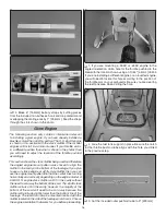
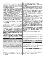
SERVO ARM
OFFSET
Pivot point
CONTROL
HORN OFFSET
When connecting pushrods and setting up your control throws,
it is
critically important
to use proper pushrod geometry—
that is the distance from the pushrod on the servo arm to the
center of the output shaft (
servo arm offset
) compared to
the distance from the pushrod on the control horn to the pivot
point (
control horn offset
).
Pushrod far out
on the servo arm…
…pushrod close in
on the control horn.
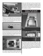
Extremely Dangerous
Pushrod Hookup
One particularly dangerous situation arises when the pushrod
on the servo arm is too “far out” and the pushrod on the
control horn is too “close in.” This setup is usually chosen by
pilots who are trying to achieve maximum, “monster” control
throws for 3D fl ight. But with your pushrods set up this way,
any free play (slop) in the linkages or servo will be greatly
magnifi ed, possibly causing destructive control surface fl utter.
Additionally, if you have to turn your ATV’s way down for
“normal” throw, the result will be poor resolution and poor
servo holding/centering capabilities. More importantly, too
much force may be transmitted back to the servo, possibly
causing control surface blowback, stripped servo gears or
stripped servo arms—the latter two likely causing a crash.
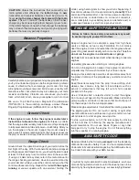
“Closest in”
on servo arm
“Farthest out”
on control horn
Preferred
Pushrod Hookup
Here is an
optimum pushrod setup—the pushrod is “close
in” on the servo arm and “far out” on the control horn. This
situation gives the greatest mechanical advantage of the
servo over the control surface which will increase the servo’s
centering capabilities and output torque, minimize any free
play in the system and allow high ATV settings for optimum
servo resolution and positive control “feel.”
Note:
When the
pushrod is “close in” on the servo arm, make certain the servo
arm can travel through its full range of movement without the
pushrod (or clevis or other type of connector) interfering with
the servo arm, output shaft or servo case.
Move the pushrod
farther out on
the servo arm…
…But leave the pushrod
in the farthest out location
on the control horn.
Acceptable
Pushrod Hookup
If the optimum situation doesn’t provide enough control throw,
the pushrod may be moved inward on the control horn, but
it’s better to go
farther out
on the servo arm because this
will introduce less free play than the alternative. Only after
moving the pushrod all the way out on the servo arm, if you
still can’t get the throw required, you’ll have to resort to moving
the pushrod closer in on the control horn.
Note:
If you have
a computer radio, it is always desirable to set your ATV’s to
100% (or as near 100% as possible to achieve the control throw
required). If setting up a model that requires extraordinary
control surface throw (for 3D fl ying for example), start by
“maxing-out” your ATV’s (typically 130% – 140%). Then, the
dual rates in your “normal” fl ight mode will still be acceptably
high (70% – 80%) for good servo resolution.
❏
2. Referring to the
Proper Pushrod Hookup
illustrations
above, adjust the location of the pushrod on the servo
arm or on the elevator horn and program the ATVs in your
transmitter to increase or decrease the throw according to
the measurements in the control throws chart.