background image

7. Install the hook side of the hook and loop fastener into

the battery compartment.

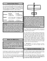
8. Secure the propeller to the prop saver using two

rubber bands. An APC or GWS 11X4.7 slow-flyer propeller
will also work for this airplane.

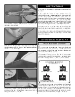
9. Drill two 1/16" holes through the fin. Route the receiver

antenna out the back of the canopy opening and “stitch” it
through the two holes in the fin.

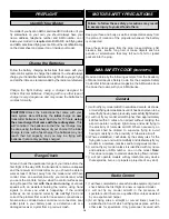
1. Use scissors or a sharp hobby knife to cut the decals from
the sheet.

2. Be certain the model is clean and free from oily
fingerprints and dust. Prepare a dishpan or small bucket with
a mixture of liquid dish soap and warm water—about one
teaspoon of soap per gallon of water. Submerse the decal in
the soap and water and peel off the paper backing. Note:
Even though the decals have a “sticky-back” and are not the
water transfer type, submersing them in soap & water allows
accurate positioning and reduces air bubbles underneath.

3. Position decal on the model where desired. Holding the
decal down, use a paper towel to wipe most of the water away.

4. Use a piece of soft balsa or something similar to squeegee
remaining water from under the decal. Apply the rest of the
decals the same way.

1. Turn on the transmitter and receiver and center the

trims. If necessary, remove the servo arms from the servos
and reposition them so they are centered. Reinstall the
screws that hold on the servo arms.

2. With the transmitter and receiver still on, check all the

control surfaces to see if they are centered. If necessary, adjust
the clevises on the pushrods to center the control surfaces.

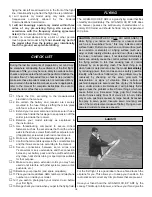
3. Make certain that the control surfaces and the speed

control respond in the correct direction as shown in the
diagram. If any of the controls respond in the wrong direction,
use the servo reversing in the transmitter to reverse the
servos connected to those controls. Be certain the control
surfaces have remained centered. Adjust if necessary.

FULL THROTTLE

RUDDER MOVES RIGHT

LEFT AILERON MOVES DOWN

RIGHT AILERON MOVES UP

ELEVATOR MOVES UP

4-CHANNEL

TRANSMITTER

(STANDARD MODE 2)

4-CHANNEL RADIO SETUP

TRANSMITTER

4-CHANNEL

TRANSMITTER

4-CHANNEL

TRANSMITTER

4-CHANNEL

Check the Control Directions

GET THE MODEL READY TO FLY

APPLY THE  DECALS

12

Summary of Contents for U-Can-Do 3D Ep

Page 1: ...y in new and unused condition to the place of purchase To make a warranty claim send the defective part or item to Hobby Services at the address below Hobby Services 3002 N Apollo Dr Suite 1 Champaign...

Page 2: ...www greatplanes com Open the Airplanes link then select the U CAN DO 3D EP ARF If there is new technical information or changes to this model a tech notice box will appear in the upper left corner of...

Page 3: ...ge lead NEVER charge through the discharge lead NEVER charge at currents greater than 1C ALWAYS set charger s output volts to match battery volts ALWAYS charge in a fireproof location NEVER trickle ch...

Page 4: ...anes com Choose Where to Buy at the bottom of the menu on the left side of the page Follow the instructions provided on the page to locate a U S Canadian or International dealer If a hobby shop is not...

Page 5: ...N Apollo Drive Suite 1 Champaign IL 61822 Telephone 217 398 8970 ext 5 Fax 217 398 7721 E mail airsupport greatplanes com KIT INSPECTION 1 Wing 2 Ailerons 2 3 Fuselage 4 Stabilizer 5 Elevator Halves 2...

Page 6: ...le between them A Run a small bead in the corner between the two parts B Use the glue gun tip to re melt the glue bead causing it to penetrate into the joint and form into a fillet The gun tip will al...

Page 7: ...removed with a hobby knife after the glue hardens 7 Test fit the ailerons to the wings If necessary enlarge the precut hinge slots with a hobby knife 8 Glue the outermost hinge into the wing making su...

Page 8: ...behind 1 Secure a 6 extension to each of your aileron servos with tape or heat shrink tubing Use the strings in the wings to pull the leads through into the cockpit area 2 Use hot melt glue to glue th...

Page 9: ...evel on the rudder 7 Cut a slot in each aileron in the location shown The front of the slots are even with the start of the hinge bevels on the ailerons 8 Press a plastic z bend clevis into each of th...

Page 10: ...ide an 80mm long 1mm carbon rod through the clevises on the servo and the control horn Adjust the linkage by sliding the rod in the clevises until you have the elevator straight when the servo is cent...

Page 11: ...hat the capacitors and brush wires are presoldered to 4 Slide the gearbox assembly onto the motor stick Line the hole in the gearbox up with the hole in the motor stick and secure it with a small wood...

Page 12: ...ost of the water away 4 Use a piece of soft balsa or something similar to squeegee remaining water from under the decal Apply the rest of the decals the same way 1 Turn on the transmitter and receiver...

Page 13: ...lift the model it means that side is heavy Balance the airplane by adding weight to the other wing tip An airplane that has been laterally balanced will track better in loops and other maneuvers Bala...

Page 14: ...to Model Aviation magazine the AMA web site or the Code that came with your AMA license 1 I will not fly my model aircraft in sanctioned events air shows or model flying demonstrations until it has b...

Page 15: ...y The U CAN DO 3D EP ARF does not however possess the self recovery characteristics of a primary R C trainer and should be flown only by experienced R C pilots For the first flight it is a good idea t...

Page 16: ...throttle always ready on the right rudder to counteract torque and climb out to make another attempt When you re ready to make your landing flare and the model is a foot or so off the deck cut your t...

Reviews: