background image

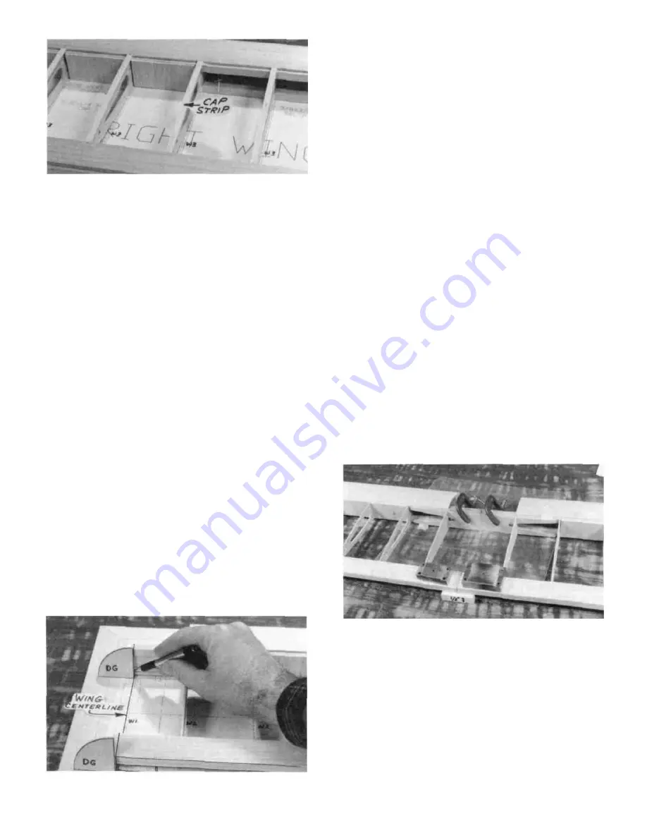
wing plan, and block up the trailing edge 1/2", using the 1/2"
x 1/2" x 2" balsa blocks. Position the die-cut 1/8" ply
dihedral gauge (DG) on the wing centerline, as shown in the
photo, and mark cut-off lines on the spars, trailing edge and
TE sheeting. Carefully cut or sand off the spars and trailing
edge at these marks.

D 3. Accurately position the left wing panel on the left

wing plan. Mark and cut off the spars and TE as in step 2.

D D 19. From the 3/32" x 1/4" x 30" balsa sticks, cut and

glue cap strips to the top of the seven outside ribs. HINT:
For easier positioning of the cap strips, first mark the location
of each rib on the LE and TE sheeting. When finished,
remove the wing from the building board and turn it over
again.

D D 20. With the wing upside down, again use the TE
jig to support the TE. Then install the bottom TE sheeting, LE

sheeting and cap strips. IMPORTANT: To insure a

straight wing, you must pin the TE securely to the TE jig
and pin the jig to the building surface while the bottom
sheeting is glued in place!

D D 21. Trim the spars and sheeting flush with the tip

rib. Cut and sand the LE sheeting and LE flush with rib
W-2. and sand the entire wing panel smooth. Sand the leading
edge to smoothly blend with the LE sheeting (see the rib
cross-section on the plan for the desired LE shape).

D 4. Lay a piece of waxed paper down at the center of the

wing, place the two wing panels together at the center, and
block up both wing tips 1/2-inch, and block up the trailing
edge 1/2-inch at the center (use the 1/2" x 1/2" x 2" balsa
blocks provided). If the spars do not mate with one another,
sand them slightly until they do.

D 5. Trial fit the die-cut 1/8" ply dihedral braces on

both sides of the spars to make sure they will readily slide
into place.

NOTE: Read steps 6 and 7, then make a "dry run'

through these steps before actually proceeding.

NOTE: 30-minute epoxy is strongly recommended
for the wing joining process.

D 22. Now go back and repeat steps 6 through 21, to build

the other wing panel. NOTE: The two wing panels are
identical, so you may build on the same plan.

JOIN THE WING PANELS

D 1. Designate one wing panel "RIGHT" and the other

"LEFT".

D 2. Accurately position the right wing panel on the right

D 6. Mix up a batch of 30-minute epoxy and smear it on

the dihedral braces, spars, spar ends, and the mating surfaces
of the trailing edge. Slide the dihedral braces in place, push
the wing panels together and immediately proceed to the
next step.

D 7. With the wing tips blocked up 1/2-inch, carefully
align the spars and TE of both wing panels. Clamp the

dihedral braces to the spars and apply a few pieces of masking
tape to hold the trailing edges in correct alignment. Wipe up
the excess epoxy with a tissue. Allow the epoxy to fully
harden before disturbing the wing.

12

Summary of Contents for Super Decathlon 40

Page 1: ...stall all R C components and flying gear engine tank pushrods etc and to test the model and fly it only with experienced competent help using common sense and in accordance with all safety standards a...

Page 2: ...ushrods 26 Control Surface Throws 29 Fitting Fuel Tank Fuelproofing 29 Install Wing Strut Straps 30 Install Receiver Switch and Battery 30 Install Main Landing Gear 30 Install Wheel Pants 31 Fit Cowl...

Page 3: ...irplane such as the Great Planes Trainer Series or Big Stick Series airplanes the Super Decathlon 40 is an excellent choice 3 You mustuse aproperR C radio that is in firstclass condition the correct s...

Page 4: ...DIE PATTERNS Usethis drawing to help you identify the die cutparts 4...

Page 5: ...2 Cycle engine but a 12x8 11x9 or 10x10 prop may be the best choices for a 4 cycle engine SELECTION OF WHEELS For maximum scale realism 2 1 4 diameter main wheels and a 1 diameter tail wheel may be u...

Page 6: ...he die cut parts are difficult to punch out do not force them Instead first cut around the parts with an Xacto knife After punching out the die cut parts use your T Bar or sanding block to lightly san...

Page 7: ...his will help to maintain symmetry when sand ing BUILD THE FIN D 6 Using a sanding block and coarse 50 or 80 grit sandpaper sand both sides of the rudder to a taper as shown on the plans The trailing...

Page 8: ...a elevators 1 8 bent wire elevator joiner D 4 Sand the leading edge to a V shape the trailing edge to a round shape and the outside edge of the tip to a round shape D 5 Temporarily tape theelevators t...

Page 9: ...avoid cutting yourself If the balsa part breaks while you are pushing on the knife the blade could go into your hand before you know it A good precaution is to wear leather gloves while performing th...

Page 10: ...ins as shown in the following sketch NOTE The spars are cut slightly too long and the excess will be cut off later D 5 Draw an accurate centerline along the rear edge of the notched balsa trailing edg...

Page 11: ...two pieces 2 1 2 long Insert one of these 1 4 x 3 4 x 2 1 2 balsa spar fillers between the top and bottom spars in the area between W l and W 2 to hold the sparsapartatthe proper spacing then glue th...

Page 12: ...LE shape D 4 Lay a piece ofwaxed paperdown at the center ofthe wing place the two wing panels together at the center and block up both wing tips 1 2 inch and block up the trailing edge 1 2 inch at th...

Page 13: ...ue the center section sheeting in place on the top and bottom as shown on the plan Sheet all the way to the front ofthe front dihedral brace D 5 Trial fit the torque rods into the center TE pieces Det...

Page 14: ...wood If this is your first time we offer the following suggested method which is the fastest and easiest we have seen D 6 Working outdoors or in a very well ventilated area apply thin CA glue to the...

Page 15: ...to the torque rods and cut as necessary until they fit D 6 Lay the ailerons on the plan and mark the hinge locations on the ailerons Place the ailerons against the wing TE and transfer the marks over...

Page 16: ...dral braces using the dowel plate holes as a drill guide The drill must extend at least 7 8 into the wing to penetrate the front and rear dihedral braces D 3 Sand one end of each wing dowel to a round...

Page 17: ...up Glue these parts together D 2 Glue the die cut 1 8 balsa lower fuse side to the upper fuse side and aft fuse side D 3 Inspect the gluejoints for gaps add thick CA glue if necessary Sand the gluejoi...

Page 18: ...is installed perpendicular to the building surface Use a carpenter s square or draftsman s triangle to insure correct installation of F 4 D 6 Now carefully align the fuse assembly on the plan Line up...

Page 19: ...alf to make two 4 1 2 lengths Glue one edge of one of these sheets to the bottom edge of the fuse side beginning at the rear edge of F 2B and extending past F 1B Wet the sheeting thoroughly with warm...

Page 20: ...s ofthe bottom sheeting at a45 degree angle to blend with the triangle stock as shown on the former cross sections on the plan This results in a shape that is reasonably close to the full size Super D...

Page 21: ...ar edge of F 2T between the cabin sides and glue in place D 12 Find the 1 4 ply wing hold down plate and trial fit it into the notches in the fuse side doublers sanding as necessary for a good fit Glu...

Page 22: ...riangles are hard balsa you may have to make several partial saw cuts with a razor saw as shown in the photo to permit easy bending Make the cuts approximately 2 apart Glue the triangles to the former...

Page 23: ...ly made Now tack glue the wing dowelplate to the uppercomers ofF 2D using acoupledrops ofthick CA and CA accelerator spray spray first then apply a drop of glue to prevent the glue from running down b...

Page 24: ...2ribs Then sand the edges of these fillers to blend with the LE and LE sheeting D 19 Trial fit the wing on the fuselage and sand thecenter nose fillers to mate with the front of the 1 8 ply cabin side...

Page 25: ...ing edge of the fin D 6 From the 3 8 balsa triangle supplied cut and se curely glue fillets under the stab at the stab fuse joint D 7 Trial fit the fin on the stab The fin trailing edge must line up w...

Page 26: ...ocations through the mount Drill 5 32 holes at the bolt locations then install the 6 32 blind nuts inside the box You may tap the blind nuts in with a hammer or pull them in using a 6 32 bolt with a f...

Page 27: ...in the rods at that point using a Z bend pliers or a standard pliers D 8 Remove the servo wheel from the servo and work theZ bendsinto thewheel NOTE Youmay havetoenlarge theservowheel holeswith a5 64...

Page 28: ...bes are not a tight friction fitonthepushrodwires apply adropofthinCAtosecure them D 19 Insert the pushrod wires into the pushrod guide tubes previously installed and attach the clevises to the elevat...

Page 29: ...17 32 balsa sheet is provided as a fuel tank base Trial fit and glue the fuel tank base in place on the bottom of the openings in the fuse side doublers NOTE We recommend locating the fuel tank so the...

Page 30: ...tailgear Insert the antenna through the tube and leave the excess length trail behind D 5 From scrap 1 8 ply make a small plate on which to mount the on offswitch Glue this plate to the front of F 3 a...

Page 31: ...the pants down to the trim line D 2 Clean the wheel pant halves with a tissue dampened with alcohol D 3 Lightly sand the inside of the wheel pants with fine sandpaper D 7 Using thick CA glue one of t...

Page 32: ...king screw location Remove the wheelpantandre drilltheholeinthealuminumLGonlywith a 1 8 drill bit Later when permanently installing the pants lock them with a 4 x 3 8 sheet metal screw D 13 Sand the e...

Page 33: ...fler to the fuselage D 2 With thewing level liftthe model by the enginepro peller shaftand the bottom oftherudder this may require two people Do this several times D 3 Ifone wing always drops when you...

Page 34: ...of ailerons 15 Bottom of ailerons 16 Top of ailerons 17 Aileron openings in wing 18 Bottom of left wing panel 19 Bottom of right wing panel 20 Top ofleft wing panel overlapcovering 1 4 atwing LE 21 To...

Page 35: ...nge and push it into the slot as most of the glue will be wiped off as it is being pushed in You must also work some glue into the slot A good way of doing this is to scoop up some epoxy with a plasti...

Page 36: ...xcess silicone sealer will squeeze out 4 Allow to dry without disturbing for atleast 24hours 5 Remove the tape then remove the wing from the saddle leaving the waxed paper orplastic wrap in place 6 Ge...

Page 37: ...e fuselage D 4 Holding a window in position on the fuse side very carefully apply medium or thick CA around the edges and hold until set D 5 To hide the glue lines you may apply 1 8 striping tape arou...

Page 38: ...dealer orborrow one from another modeler With the wing mounted to the fuselage use the incidence meter to check the angle of your wing at the root and at the tips Ifthe incidence meter reveals awing t...

Page 39: ...Keep your face and body as well as all spectators away from the plane ofrotation ofthe propeller as you startand run the engine Keep items such as these away from the prop loose clothing shin sleeves...

Page 40: ...ence Add and practice one maneuverata time learning how it behaves in each one If you notice any sluggishness in the way your Super Decathlon 40 handles it is probably a resultofnot enough speed in w...

Page 41: ...ge until the stabilizer or stab bed is perfectly level use a small bubble level 2 With the fuselage level use an incidence meter to check the wing angle The wing must be set at 1 degree positive Adjus...

Page 42: ...42...

Page 43: ...43...

Page 44: ...ft Rochester WI Pete Myers modifications are listed in the instructions and shown on the plan The major differences between Pete s airplane and the 3 view are 1 Clipped wing tips 2 Trim on the bottom...

Reviews: