GREAT PLANES SlowPoke Sport 40 Instruction Manual Download Page 28

Balance your propellers carefully before flying. An
unbalanced prop is the single most significant cause of
damaging vibration. Not only will engine mounting screws
and bolts vibrate out, possibly with disastrous effect, but
vibration will also damage your radio receiver and battery.
Vibration will cause your fuel to foam, which will, in turn,
cause your engine to run rough or quit.

We use a 

Top Flite Precision Magnetic Prop Balancer

(#TOPQ5700) in the workshop and keep a 

Great Planes

Fingertip Balancer

(#GPMQ5000) in our flight box.

If you have dual rates on your transmitter, set the switches
to  “high rate” for takeoff, especially when taking off in a
crosswind. Although this model has excellent low speed
characteristics, you should always build up as much speed
as your runway will permit before lifting off, as this will give
you a safety margin in case of a “flame-out.” Start your
takeoff roll pointing directly into the wind if possible. When
you first advance the throttle and the tail begins to lift, the
plane will start to turn left (a characteristic of all “tail
draggers”). Be ready for this and correct by applying
sufficient right rudder to hold it straight down the runway.
The left-turning tendency will go away as soon as the tail is
up and the plane picks up speed. Be 

sure

to allow the tail

to come up. Don’t hold the tail on the ground with too much
up elevator, as the SlowPoke Sport 40 will become airborne
prematurely and will possibly stall. When the plane has
sufficient flying speed, (this should only take 50’ or so on a
paved surface, about 100’ off short grass!) lift off by
smoothly applying up elevator (don’t  “jerk” it into a steep
climb!) and climb out gradually.

We recommend that you take it easy with your SlowPoke
Sport 40 for the first several flights, gradually “getting
acquainted” with this classic sport plane as your engine

gets fully broken-in. Add and practice one maneuver at a
time, learning how she behaves in each. For ultra-smooth
flying and normal maneuvers, we recommend using the
“low rate” settings as listed on page 26. “High rate” elevator
may be required for rolls, spins and tight loops.

When it’s time to land, fly a normal landing pattern and
approach into the wind. Always try to land directly into the
wind as directional control is much easier and you don’t
have to worry about the wind getting under one of those
huge wing panels and possible flipping it over. Keep a few
clicks of power on until you are over the runway threshold.
For your first landings, plan to land slightly faster than stall
speed and on the main wheels, as this is the easiest way to
land your SlowPoke Sport 40. Later, with a little technique,
you will find you can make slow, 3-point landings.

Have a ball! But always stay in control and fly in a safe
manner.

GOOD LUCK AND GREAT FLYING!

Landing

CAUTION

(THIS APPLIES TO ALL R/C AIRPLANES): If,

while flying, you notice any unusual sounds, such as a low-
pitched “buzz,” this may be an indication of control surface
“flutter.” Because flutter can quickly destroy components of
your airplane, any time you detect flutter you must

immediately

cut the throttle and land the airplane! Check

all servo grommets for deterioration (this will indicate which
surface fluttered) and make sure all pushrod linkages are
slop-free. If it fluttered once, it probably will flutter again
under similar circumstances unless you can eliminate the
slop or flexing in the linkages. Here are some things which
can result in flutter: Excessive hinge gap; Not mounting
control horns solidly; Sloppy fit of clevis pin in horn;
Elasticity present in flexible plastic pushrods; Side-play of
pushrod in guide tube caused by tight bends; Sloppy fit of
Z-bend in servo arm; Insufficient glue used when gluing in
the elevator joiner wire or aileron torque rod; Excessive
flexing of aileron, caused by using too soft balsa aileron;
Excessive “play” or “backlash” in servo gears; and insecure
servo mounting.

Flight

Takeoff

Balance the Propeller

Summary of Contents for SlowPoke Sport 40

Page 1: ...o liability shall be assumed nor accepted for any damage resulting from the use by the user of the final user assembled product By the act of using the user assembled product the user accepts all resu...

Page 2: ...solo Your local hobby shop has information about flying clubs in your area whose membership includes qualified instructors You can also contact the national Academy of Model Aeronautics AMA which has...

Page 3: ...ch put a new blade in your hobby knife and let s build a SlowPoke Sport 40 4 Channel radio with 5 servos Engine 32 46 2 stroke 48 52 4 stroke Propeller Top Flite Power Point 10 oz Fuel tank Great Plan...

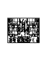
Page 4: ...4 D I E C U T P L Y P A T T E R N S...

Page 5: ...5 Use this drawing or photocopy it and use the copy to design your trim scheme...

Page 6: ...fuselage wing fin rudder and stab stabilizer Zipper top food storage bags are handy to store your parts as you sort identify and separate them into sub assemblies Get Ready to Build 1 64 4mm 1 32 8mm...

Page 7: ...plan 3 Using a 1 4 x 1 4 x 24 balsa stick measure cut and glue all cross bracing for the rudder in position Remove the pins and sand both sides of the rudder smooth 4 Measure and cut the leftover 1 4...

Page 8: ...osition From 1 4 x 1 4 x 24 balsa measure cut and glue the cross bracing in position to complete the stab assembly Remove the stab from the board and sand both sides smooth Blend the leading edge at t...

Page 9: ...e wing plan with wax paper or Plan Protector and let s get going on the center section of the wing NOTE The wing panels are built right side up over the plan Work on a flat surface over the plan cover...

Page 10: ...all all of the top spars and glue them in place while checking that the ribs remained vertical 8 From two 1 16 x 3 4 x 36 balsa sub leading edges cut a piece 4 3 8 long from each Glue this piece to th...

Page 11: ...e die cut patterns on pages 4 and 5 and the plan to identify and position the parts 1 Locate four 3 32 die cut balsa W 3 ribs and six 1 8 die cut ply W 3A landing gear rail doublers LGD Using thick CA...

Page 12: ...the spars at the tip end Allow them to protrude past the last rib 8 Starting with the W 3 rib with two doublers not the root rib glue all ribs except the root rib in position with thin CA Work toward...

Page 13: ...hold it flat 15 Use thick CA to glue a sheet of 1 16 x 3 x 30 balsa to the top leading edge of the wing panel from the root end extending over the tip The sheet should fit against the rear edge of th...

Page 14: ...ing TE 22 Using the plan for reference measure cut and glue leftover pieces of 1 4 x 1 4 x 1 1 2 balsa stick to the inside of the wing TE and aileron LE to provide more surface area for the hinge slot...

Page 15: ...root rib Carefully cut the root rib to allow the wing joiners to pass through Without gluing test fit the outer and center sections together Make any adjustments as necessary for a good fit We will j...

Page 16: ...cut a 1 8 x 1 2 x 36 balsa stick to make the top and bottom longerons Glue these sticks to the forward fuse side and the stab saddle Cut a short piece of leftover 1 8 x 1 2 balsa stick to fit between...

Page 17: ...all joints to permanently glue the fuse together Apply medium or thick CA if needed to fill any small gaps 13 Cut two 36 outer pushrod tubes to 22 Sand the surface of the tubes with 80 grit sandpaper...

Page 18: ...3 4 machine screws and 4 washers Apply a drop of thin CA to each blind nut flange to hold them in place Don t get CA into the threads 19 Use a 3 32 x 3 x 36 to sheet the bottom of the fuse from the w...

Page 19: ...nding bar to do as much of the shaping as you can before gluing it in place Once satisfied with the shape and fit glue the turtle deck top to the top of the aft fuse formers and the tail post 27 Measu...

Page 20: ...he fuse Cut a slot in the center of the tail post to accept the tail gear bearing Hint A Great Planes Slot Machine motorized slotting tool works great for this operation 3 Temporarily install the bear...

Page 21: ...dings and the forward end of the pushrod tube exit slots with balsa filler Sand the entire structure with progressively finer grades of sandpaper ending with 320 grit Fuelproofing may be done either...

Page 22: ...sides 12 Fuse top 13 Ends of ailerons 14 Bottom of ailerons 15 Top of ailerons 16 Bottom of left wing panel 17 Bottom of right wing panel 18 Top of left wing panel overlap 1 4 at wing LE 19 Top of rig...

Page 23: ...rily attach the control surface to verify the fit and operation 4 Rather than just making a single slit it is better to cut away a narrow rectangle of covering to provide an adequate opening for the C...

Page 24: ...rudder see sketch above for correct alignment The pushrod should not be bent and should slide easily in the tube Mark the location for the horn screws on the control surface Drill the 3 32 horn screw...

Page 25: ...ess 13 Turn on the radio system and check the direction of all control functions They must all move in the direction shown in the sketch If not change the position of the reversing switches on your tr...

Page 26: ...in your radio instruction manual You should always charge your transmitter and receiver batteries the night before you go flying and at other times as recommended by the radio manufacturer The best p...

Page 27: ...ed events air shows or model flying demonstrations until it has been proven to be airworthy by having been previously successfully flight tested 2 I will not fly my model aircraft higher than approxim...

Page 28: ...nd practice one maneuver at a time learning how she behaves in each For ultra smooth flying and normal maneuvers we recommend using the low rate settings as listed on page 26 High rate elevator may be...

Page 29: ...B C...

Page 30: ...D A...

Reviews: