GREAT PLANES SlowPoke Sport 40 Instruction Manual Download Page 19

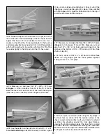
24. Slide the tailpost of the vertical fin into position at the

rear of the fuse. The forward edge of the fin should be flush
against the back of F6 and centered side to side. Use a
square to check that the fin is perpendicular to the fuse top
and make adjustments as needed if it is not. When satisfied
with the fit, glue the fin in position with thick CA. Pinch the
fuse sides tightly to the tail post until the CA has cured.

25. Measure, cut and glue the 1/8” x 3/8” x 24” balsa

stringers

to fit the turtle deck from F4 to the TE of the fin.

Bevel the rear end of each stick to fit flush with the tail post.
(See inset photo of bevel) Fit all 6 stringers at this time.

26. Use the pattern on the plan to cut the 5/16” x 2” x 24”

balsa 

turtle deck top

to size. Work slowly to obtain a good

fit. Use a razor plane and sanding bar to do as much of the
shaping as you can before gluing it in place. Once satisfied
with the shape and fit, glue the turtle deck top to the top of
the aft fuse formers and the tail post.

27. Measure, cut and glue the three 1/8” x 3/8” x 12” balsa

stringers

to fit between F1A and F3A. Measure, cut and

glue the 1/8” x 1/8” x 36” balsa gluing stringer into the
notches at the bottom of F1A - F3A and up to F4A. (See
photo at step 29.)

28. Cut a sheet of 3/32” x 3” x 36” balsa to make three

pieces 12” long. Edge glue the three pieces together
making a 3/32” x 9” x 12” piece.

29. Rub a piece of colored chalk along the top edges of

the lower fuse as shown. Wet the outside surface of the
sheet you just made and flex it with your hands to 

soften it

up. Wrap the sheeting around the front deck formers,
pressing the bottom edges against the fuse that is coated
with chalk. Remove the sheet and cut along the chalk lines.
Recheck the fit and adjust as needed. When satisfied with
the fit, glue the sheet in place with medium CA.

19

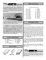
Summary of Contents for SlowPoke Sport 40

Page 1: ...o liability shall be assumed nor accepted for any damage resulting from the use by the user of the final user assembled product By the act of using the user assembled product the user accepts all resu...

Page 2: ...solo Your local hobby shop has information about flying clubs in your area whose membership includes qualified instructors You can also contact the national Academy of Model Aeronautics AMA which has...

Page 3: ...ch put a new blade in your hobby knife and let s build a SlowPoke Sport 40 4 Channel radio with 5 servos Engine 32 46 2 stroke 48 52 4 stroke Propeller Top Flite Power Point 10 oz Fuel tank Great Plan...

Page 4: ...4 D I E C U T P L Y P A T T E R N S...

Page 5: ...5 Use this drawing or photocopy it and use the copy to design your trim scheme...

Page 6: ...fuselage wing fin rudder and stab stabilizer Zipper top food storage bags are handy to store your parts as you sort identify and separate them into sub assemblies Get Ready to Build 1 64 4mm 1 32 8mm...

Page 7: ...plan 3 Using a 1 4 x 1 4 x 24 balsa stick measure cut and glue all cross bracing for the rudder in position Remove the pins and sand both sides of the rudder smooth 4 Measure and cut the leftover 1 4...

Page 8: ...osition From 1 4 x 1 4 x 24 balsa measure cut and glue the cross bracing in position to complete the stab assembly Remove the stab from the board and sand both sides smooth Blend the leading edge at t...

Page 9: ...e wing plan with wax paper or Plan Protector and let s get going on the center section of the wing NOTE The wing panels are built right side up over the plan Work on a flat surface over the plan cover...

Page 10: ...all all of the top spars and glue them in place while checking that the ribs remained vertical 8 From two 1 16 x 3 4 x 36 balsa sub leading edges cut a piece 4 3 8 long from each Glue this piece to th...

Page 11: ...e die cut patterns on pages 4 and 5 and the plan to identify and position the parts 1 Locate four 3 32 die cut balsa W 3 ribs and six 1 8 die cut ply W 3A landing gear rail doublers LGD Using thick CA...

Page 12: ...the spars at the tip end Allow them to protrude past the last rib 8 Starting with the W 3 rib with two doublers not the root rib glue all ribs except the root rib in position with thin CA Work toward...

Page 13: ...hold it flat 15 Use thick CA to glue a sheet of 1 16 x 3 x 30 balsa to the top leading edge of the wing panel from the root end extending over the tip The sheet should fit against the rear edge of th...

Page 14: ...ing TE 22 Using the plan for reference measure cut and glue leftover pieces of 1 4 x 1 4 x 1 1 2 balsa stick to the inside of the wing TE and aileron LE to provide more surface area for the hinge slot...

Page 15: ...root rib Carefully cut the root rib to allow the wing joiners to pass through Without gluing test fit the outer and center sections together Make any adjustments as necessary for a good fit We will j...

Page 16: ...cut a 1 8 x 1 2 x 36 balsa stick to make the top and bottom longerons Glue these sticks to the forward fuse side and the stab saddle Cut a short piece of leftover 1 8 x 1 2 balsa stick to fit between...

Page 17: ...all joints to permanently glue the fuse together Apply medium or thick CA if needed to fill any small gaps 13 Cut two 36 outer pushrod tubes to 22 Sand the surface of the tubes with 80 grit sandpaper...

Page 18: ...3 4 machine screws and 4 washers Apply a drop of thin CA to each blind nut flange to hold them in place Don t get CA into the threads 19 Use a 3 32 x 3 x 36 to sheet the bottom of the fuse from the w...

Page 19: ...nding bar to do as much of the shaping as you can before gluing it in place Once satisfied with the shape and fit glue the turtle deck top to the top of the aft fuse formers and the tail post 27 Measu...

Page 20: ...he fuse Cut a slot in the center of the tail post to accept the tail gear bearing Hint A Great Planes Slot Machine motorized slotting tool works great for this operation 3 Temporarily install the bear...

Page 21: ...dings and the forward end of the pushrod tube exit slots with balsa filler Sand the entire structure with progressively finer grades of sandpaper ending with 320 grit Fuelproofing may be done either...

Page 22: ...sides 12 Fuse top 13 Ends of ailerons 14 Bottom of ailerons 15 Top of ailerons 16 Bottom of left wing panel 17 Bottom of right wing panel 18 Top of left wing panel overlap 1 4 at wing LE 19 Top of rig...

Page 23: ...rily attach the control surface to verify the fit and operation 4 Rather than just making a single slit it is better to cut away a narrow rectangle of covering to provide an adequate opening for the C...

Page 24: ...rudder see sketch above for correct alignment The pushrod should not be bent and should slide easily in the tube Mark the location for the horn screws on the control surface Drill the 3 32 horn screw...

Page 25: ...ess 13 Turn on the radio system and check the direction of all control functions They must all move in the direction shown in the sketch If not change the position of the reversing switches on your tr...

Page 26: ...in your radio instruction manual You should always charge your transmitter and receiver batteries the night before you go flying and at other times as recommended by the radio manufacturer The best p...

Page 27: ...ed events air shows or model flying demonstrations until it has been proven to be airworthy by having been previously successfully flight tested 2 I will not fly my model aircraft higher than approxim...

Page 28: ...nd practice one maneuver at a time learning how she behaves in each For ultra smooth flying and normal maneuvers we recommend using the low rate settings as listed on page 26 High rate elevator may be...

Page 29: ...B C...

Page 30: ...D A...

Reviews: