❏ ❏
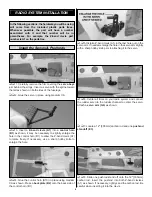
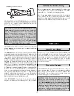
1. Carefully remove the film covering the servo bays
just behind the wings. Insert a servo with the spline toward
the tail as shown on both sides of the fuselage.
❏ ❏
2. Glue the servo in place using medium CA.
❏ ❏
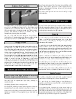
3. Insert a Z-bend clevis (A1) into a control horn
(B1) as shown. It may be necessary to slightly enlarge the
hole in the control horn (B1) to allow the Z-bend clevis (A1)
to rotate freely. If necessary, use a sharp hobby knife to
enlarge the hole.
❏ ❏
4. Glue the control horn (B10) in place using medium
CA as shown. Press a backplate (B2) onto the back side of
the control horn (B1).
❏ ❏
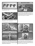
5. Install a Z-bend clevis (A1) in the last hole out on the
servo arm. If needed, enlarge the hole in the servo arm slightly
with a sharp hobby knife prior to attaching it to the servo.
❏ ❏
6. Center all trims on your radio system and connect
the rudder servo to the rudder channel to center the servo.
Attach a servo arm (G6) as shown.
❏ ❏
7. Locate a 12" [305mm] carbon rod and one pushrod
standoff (E3).
❏ ❏
8. Slide one pushrod stand off onto the 12" [305mm]
carbon rod. Insert the pushrod into both Z-bend clevises
(A1) as shown. If necessary, lightly sand the carbon rod. Be
careful when inserting it into the clevis.
Install the Servos & Pushrods
In the following sections, the hardware you will be using
will come from the included plastic parts trees.
Whenever possible, the part will have a number
associated with it and that number will be in
parentheses. For example, the Z-bend clevis part
number is A1 on the parts tree.
RADIO SYSTEM INSTALLATION
9

