background image

❏ 

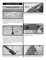
1. The areas where you will be mounting your receiver,

speed control, and battery must have a thin coating of glue
to allow the Velcro to attach. You can use CA or any type of
wood glue for this purpose. Allow the glue to dry or cure
completely before attaching the Velcro. Note the location of
the mounted speed control in the above photograph.

❏ 

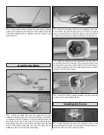
2. The photograph illustrates the placement of the

receiver. Place a 1/16" [1.6mm] hole close to the receiver in
the bottom of the fuselage. Feed the antenna through this
hole and tape it into place on the wing.

❏ 

3. Note the installation and position of the battery pack.

❏ 

4. Install the hatch.

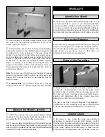
1. Use scissors or a sharp hobby knife to cut the decals from
the sheet.

2. Be certain the model is clean and free from oily
fingerprints and dust. Prepare a dishpan or small bucket
with a mixture of liquid dish soap and warm water–about
one teaspoon of soap per gallon of water. Submerse the
decal in the soap and water and peel off the paper backing
while the decal is in the soapy water. Note: Even though the
decals have a “sticky-back” and are not the water transfer
type, submersing them in soap & water allows accurate
positioning and reduces air bubbles underneath.

3. Position decal on the model where desired. Hold the
decal down and use a paper towel to wipe most of the
water away.

4. Use a piece of soft balsa or something similar to
squeegee remaining water from under the decal. Apply the
rest of the decals the same way.

Note: For safety reasons, remove the propeller from the
airplane before proceeding.

❏ 

1. Turn on the transmitter and receiver and center the

trims. If necessary, remove the servo arms from the servos
and reposition them so they are centered. Reinstall the
screws that hold on the servo arms.

❏ 

2. While the transmitter and receiver are still on, check all the

control surfaces to see if they are centered. If necessary, adjust
the clevises on the pushrods to center the control surfaces.

❏ 

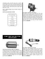
3. Make certain that the control surfaces respond in the

correct direction as shown in the diagram. If any of the
controls respond in the wrong direction, use the servo

4-CHANNEL

TRANSMITTER

TRANSMITTER

4-CHANNEL

TRANSMITTER

4-CHANNEL

TRANSMITTER

4-CHANNEL

Check the Control Directions

GET THE MODEL READY TO FLY

Apply the Decals

Installing the Receiver

& Speed Control

11

Summary of Contents for Micro Whizz

Page 1: ...bled product By the act of using the user assembled product the user accepts all resulting liability If the buyer is not prepared to accept the liability associated with the use of this product the bu...

Page 2: ...p www greatplanes com airplanes index html 1 Your Great Planes Micro Whizz ARF should not be considered a toy but rather a sophisticated working model that functions very much like a full size airplan...

Page 3: ...best fit Whenever the term glue is written you should rely upon your experience to decide what type of glue to use When a specific type of adhesive works best for that step the instructions will make...

Page 4: ...eron cannot be purchased separately but is only available with the wing kit Replacement parts are not available from Product Support but can be purchased from hobby shops or mail order Internet order...

Page 5: ...make sure it is complete and inspect the parts to make sure they are of acceptable quality If any parts are missing or are not of acceptable quality or if you need assistance with assembly contact Gre...

Page 6: ...re that the bracket is flush with the rear of the tail boom and the pre cut slot in the bracket is facing toward the rear When satisfied with the fit glue the bracket into place using medium CA 3 With...

Page 7: ...sitioning with a ruler in the same way as when you marked the location 10 Cut a slot into the right elevator at a point 3 16 5mm toward the outer end of the elevator from the inside edge of the elevat...

Page 8: ...ply CA inside the hole Then return the tail assembly to the correct position Make sure that the position is right before the CA has cured 1 As shown in the photograph above install the two control hor...

Page 9: ...our before proceeding 2 When the adhesive has cured completely insert the motor all the way into the gear drive unit This is a tight fit and you will also have to move the gear box back and forth to a...

Page 10: ...rudder and elevator pushrods into the slot in the tail boom Snap the clevis onto the elevator and rudder control horns as shown in the photograph above 6 Position the rudder so that it is directly ali...

Page 11: ...a sticky back and are not the water transfer type submersing them in soap water allows accurate positioning and reduces air bubbles underneath 3 Position decal on the model where desired Hold the dec...

Page 12: ...make it more difficult to slow for landing Moving the C G aft makes the model more maneuverable but could also cause it to become too difficult to control In any case start at the recommended balance...

Page 13: ...tter in loops and other maneuvers No matter if you fly at an AMA sanctioned R C club site or if you fly somewhere on your own you should always have your name address telephone number and AMA number o...

Page 14: ...dels fly in the proximity of full scale aircraft 3 Where established I will abide by the safety rules for the flying site I use and I will not willfully and deliberately fly my models in a careless re...

Page 15: ...lower speeds Add power to see how she climbs as well Continue to fly around executing various maneuvers and making mental notes or having your assistant write them down of what trim or C G changes may...

Page 16: ...Fly S 280 Gearbox Developed for low noise and low maintenance this Great Planes ElectriFly gearbox features a 5 1 gear ratio and uses standard bronze bushings for long lasting sport use A lightweight...

Reviews: