10
GET THE MODEL READY TO FLY
Check the Control Directions
❏
1. Connect the motor battery and turn on the transmitter
and receiver and center the trims. Make sure the elevator and
rudder are centered. If necessary, adjust the pushrods in the
screw-lock connectors and center the elevator and rudder.
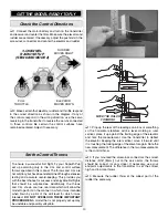
FULL
THROTTLE
ELEVATOR
MOVES DOWN
RUDDER
MOVES RIGHT
3-CHANNEL
RADIO SET UP
(STANDARD MODE 2)
❏
2. Make certain that elevator, rudder and throttle respond
in the correct direction as shown in the diagram. If any of
the controls respond in the wrong direction, use the servo
reversing in the transmitter to reverse the servos connected
to those controls. Be certain the control surfaces have
remained centered. Adjust if necessary.
Set the Control Throws
To ensure a successful fi rst fl ight, fl y your Sopwith Pup
set up according only to the C.G. and control surface
throws specifi ed in this manual. The throws and C.G. are
not arbitrary, but have been determined through extensive
testing and accurate record-keeping. This provides you
with the best chance for success and enjoyable fi rst fl ights
that should be surprise-free. Additionally, the throws
and C.G. shown are true, real data which will allow the
model to perform in the manner in which it was intended
when fl own by a pilot of the skill level for which it was
intended.
DO NOT OVERLOOK THESE IMPORTANT
PROCEDURES.
A model that is not properly set up may
be unstable and possibly unfl yable.
MOVE THE RULER
FORWARD
❏
1. Prop up the rear of the fuselage on a box or something
so the horizontal stabilizer will be level. Holding a ruler
vertical, place it up against the trailing edge of the elevator
and note the measurement. Use the transmitter to defl ect
the elevator. Keeping the ruler vertical, move it forward until
it is touching the trailing edge of the elevator again. Note the
new measurement. The difference in the two measurements
is the control throw.
❏
2. If you mounted the screw-lock connectors the correct
distance (5/16" [8mm]) out on the servo arms, the throws
should be correct (or very close). If necessary, use your
endpoint adjustments in the transmitter to set the correct
high and low rate throws.
❏
3. Measure the rudder throw at the widest part of the
rudder the same way.


