background image

Great Plains Manufacturing, Inc.

Table of Contents

Main Seed Box Planting

3

02/22/2019

Table of Contents

202-578B

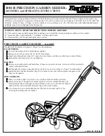
Changing Double Sprocket

Set this identically on the gauge wheel of each wing.

Refer to Figure 2

4. Loosen idlers   and  , and remove both chains 

from double sprocket  .

5. Remove retaining pin   from shaft.

6. Remove sprocket   from shaft, and reverse orienta-

tion of which disk is in/out.

7. Replace sprocket   on shaft and re-pin  .
8. Place chains back on sprockets.

9. Re-engage idlers and tighten, leaving 

3

4

in slack in 

forward span of chain  .

10. If jackshaft sprocket does not need to be changed, 

skip to step 17.

Null4:

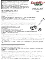
Changing Jackshaft Sprocket

Set this identically on the gauge wheel of each wing. it 

may be necessary to shorten or lengthen the upper 

chain. It has removable links for this purpose.

Refer to Figure 3

When re-assembling a chain, make sure the open end of 

the clip faces away from the direction of chain travel, to 

reduce chain fouling from debris caught in the clip.

Refer to Figure 4

11. If the double sprocket did not need to be changed, 

loosen upper idler (  in Figure 2)

12. Remove chain from jackshaft sprocket  .

13. Loosen set screws   on both upper sprockets (only 

one of two shown in figure).

14. Slide current sprocket aside. Position it so that it 

does not rub on any fixed machine parts. Re-tighten 

the set screw.

15. Slide new sprocket into approximate position.

16. Re-mount chain, and align sprocket   so that chain 

is perpendicular to the jackshaft (parallel to the 
ground drive frame). Tighten set screw  .

17. Re-engage idler   and tighten it until there is 

1

2

in 

slack in the forward span.

1

Figure 2

Double Sprocket

16409

4

5

3

6

3

4

1

5

1

1

5

6

Figure 4

Jackshaft Sprockets

16412

2

8

7

3

2

7

2

7

3

Summary of Contents for 2SNG24

Page 1: ...ate Charts for 2007 2SNG24 and 2SNG30 Native Grass Drills The following pages are to assist in the proper setting of seeding and fertilizer application rates for the 24ft and 30ft Native 2 Section dri...

Page 2: ...0 Implement s Table of Contents Master Page Blank Table of Contents 02 22 2019 Blank...

Page 3: ...tri Pro Seed Lok Solid Stand Terra Guard Turbo Chisel Turbo Chopper Turbo Max Turbo Till Ultra Till Whirlfilter and Yield Pro Brand and Product Names that appear and are owned by others are trademarks...

Page 4: ...Cover Master Page Blank Cover...

Page 5: ...ator s Manual Have both available when preparing to plant Setting Planting Rate There are four steps to obtaining the desired number of seeds per acre 1 Know the characteristics of the seed Consult yo...

Page 6: ...d cups seed tubes and drives are work ing properly and free from foreign material Select the drive type from the seed rate charts The drive type varies by seed type and intended population Refer to Fi...

Page 7: ...hain It has removable links for this purpose Refer to Figure 3 When re assembling a chain make sure the open end of the clip faces away from the direction of chain travel to reduce chain fouling from...

Page 8: ...n row unit adjust ments without planting seed Position Seed Cup Doors Set this identically for each row Refer to Figure 6 which depicts the seed cup door handle in position At each seed box seed tube...

Page 9: ...s stored on a stob present at top front center of either wing frame 4 Fill three or more compartments at least 1 2 full of seed in the main seed box Pull seed hoses off open ers under the compartments...

Page 10: ...the wing now calibrated 13 Re attach the seed tubes on the tested rows Return the calibration crank to the storage stob of the wing customarily used for calibration Note When drilling check the amoun...

Page 11: ...56 62 68 75 82 89 94 99 102 107 111 10 inch 0 5 8 12 15 20 24 28 33 37 42 46 51 56 61 67 71 74 77 80 83 Drive Type Seed Rate Handle Setting 2 0 5 10 15 20 25 30 35 40 45 50 55 60 65 70 75 80 85 90 95...

Page 12: ...26 29 31 34 37 40 42 42 42 10 inch 0 2 3 4 6 7 9 11 13 14 16 18 19 21 23 26 28 30 31 32 32 Drive Type Seed Rate Handle Setting 2 0 5 10 15 20 25 30 35 40 45 50 55 60 65 70 75 80 85 90 95 100 Rows Seed...

Page 13: ...1 59 63 98 72 74 78 80 10 inch 0 4 6 9 12 15 17 21 23 26 29 32 35 39 44 47 51 54 56 58 60 Drive Type Seed Rate Handle Setting 1A 0 5 10 15 20 25 30 35 40 45 50 55 60 65 70 75 80 85 90 95 100 Rows Seed...

Page 14: ...nch 0 0 0 1 2 3 4 5 6 7 8 9 10 11 12 14 14 15 16 17 17 Drive Type Seed Rate Handle Setting 1 0 5 10 15 20 25 30 35 40 45 50 55 60 65 70 75 80 85 90 95 100 Rows Seed Rate in Pounds Per Acre based on 60...

Page 15: ...r shifted into place Before setting the drive type rotate the gauge wheels Check that seed cups seed tubes and drives are work ing properly and free from foreign material Select the drive type from th...

Page 16: ...le links for this purpose Refer to Figure 10 When re assembling a chain make sure the open end of the clip faces away from the direction of chain travel to reduce chain fouling from debris caught in t...

Page 17: ...at your adjusted value 2 Record the weight of an empty container large enough to hold seed metered from the native grass box 3 Raise drill to get drive wheel off the ground To cali brate using calibra...

Page 18: ...d repeat the calibration pro cedure 12 Set the other wing to match the wing now calibrated 13 Re attach the seed tubes on the tested rows Return the calibration crank to the storage stob of the wing c...

Page 19: ...15 20 25 30 35 40 45 50 55 60 65 70 75 80 85 90 95 100 Rows Seeding Rate in Pounds per Acre 7 5 inch 0 0 0 5 0 9 1 4 2 1 2 6 3 3 4 0 4 7 5 3 5 8 6 3 6 7 7 2 7 6 8 2 8 8 9 3 9 8 10 4 10 inch 0 0 0 4 0...

Page 20: ...r Acre 7 5 inch 0 0 0 9 1 6 2 6 3 9 4 9 6 1 7 4 8 6 9 8 11 1 12 5 13 7 14 9 16 3 17 6 18 8 20 4 21 9 23 5 10 inch 0 0 0 6 1 5 1 9 2 5 3 6 4 5 5 4 6 3 7 2 8 1 9 1 10 0 10 9 12 0 12 9 13 8 14 9 16 1 17...

Page 21: ...rockets The drill s revolutions per acre at the native grass cup allows you to calibrate the output in pounds by cup sprocket revolution per acre The pounds per acre in the seed charts are based on dr...

Page 22: ...mple on page 20 11 Weigh metered seed and subtract the initial weight of the container Divide this number by 3 number of cups metered 12 Multiply by the number of openers on the drill This equals the...

Page 23: ...may want to repeat the calibration procedure if your results vary greatly from the seed rate chart Note All native grass mixes will vary in weight seed type and density so this is why you must calibra...

Page 24: ...a 48 row 7 5in 2SNG30 In the chart on page 22 find the Cup Revolutions Per Acre for the tested configuration The table cell at Drive Type 1 19T Driving 15T Driven is 155 17 Calculate the Sampled poun...

Page 25: ...s needed Great Plains Graphite Lubricant 821 042C 1 lb bottle 821 060C 5 lb jug NG Driving Sprocket 15 15 15 19 19 35 30 30 NG Driven Sprocket 30 24 19 19 15 24 19 15 Drive Type Seed Cup Revolutions p...

Page 26: ...r to Figure 18 4 To calibrate using calibration crank disengage gauge wheel lockout and attach calibration crank to coupler on left hand side of gauge wheel jackshaft using retaining pin 5 Turn gauge...

Page 27: ...e storage stob of the wing customarily used for calibration When drilling check the amount of seed you are using by noting the acres drilled amount of seed added to drill and the level of seed in the...

Page 28: ...15 15 15 19 19 35 30 30 NG Driven Sprocket 30 24 19 19 15 24 19 15 Drive Type Pounds per Acre 1 21 26 33 42 53 61 66 83 1A 43 53 67 85 108 125 135 171 2 7 8 11 14 17 20 21 27 2A 14 17 22 28 35 41 44...

Page 29: ...Table of Contents Master Page Blank Table of Contents Blank Blank...

Page 30: ...Great Plains Manufacturing Inc Corporate Office P O Box 5060 Salina Kansas 67402 5060 USA 2 Table of Contents Master page EOD EOD EOD...

Reviews: