WMCM, WDX, WM, WD,15WM, WE,
WLP & NEMA 12K Series Wall Mounts
Installation Instructions
GreatCabinets.com -
1.866.879.4522
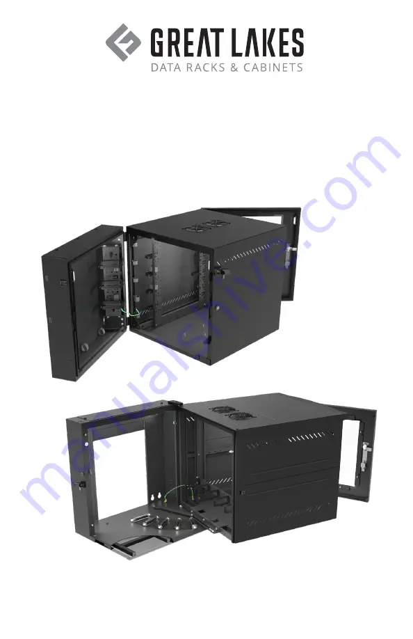
WMCM
WDX
Page 1: ...WMCM WDX WM WD 15WM WE WLP NEMA 12K Series Wall Mounts Installation Instructions GreatCabinets com 1 866 879 4522 WMCM WDX...
Page 2: ...eat Lakes wall mount could result in equipment damage serious injury or possible death Only trained service personnel should be used to remove the wall mount from its packaging Also be sure you have a...
Page 3: ...lat and square in the horizontal and vertical plane to ensure the Great Lakes wall mount closes correctly If the wall is not flat and square the use of shims may be required Wood studded wall mounting...
Page 4: ...3 25 350 GL15WM 15 38 22 25 17 66 7 100 GL24WE 24 00 36 10 20 50 10 350 GL GL24WLP 24 00 27 00 10 00 4 105 GL GL36WLP 36 00 27 00 10 00 4 105 GL GL48WLP 48 00 27 00 10 00 4 105 GL240N12 24 00 24 00 24...
Page 5: ...ain protective grounding stud located inside on the back of the rear section using a listed ring or closed loop terminal Connect the wall mount frame on the WE and 15WM Series to the main protective g...
Page 6: ...centric conduit knockouts on top bottom and non hinged side of rear section Heavy duty hinges Front door Center swing section Offset 19 EIA mounting rails 2 pairs tapped 12 24 Independent locking fron...
Page 7: ...28 00 23 38 Max rail spacing 3 41 Max cable area width Optional 1 4 turn D ring Square holes for CM 25 1 4 turn D rings 12 24 UNC 2B 63 63 50 1 75 PATTERN REPEATS Cable management tie points on rails...
Page 8: ...tom of center section guide bracket should be oriented with handle and pointing up Remove center section of gasket on now bottom of rear section Move receiving bracket to now top of rear section Add a...
Page 9: ...with 1 2 and 3 nominal concentric conduit knockouts Front door frame with optional inserts solid steel mesh or plexi Center swing section Rear section mounts to wall Independent locking front door rea...
Page 10: ...0 93 MAX RAIL SPACING 17 70 OPENING 4 13 OPENING 3 94 2 56 50 63 63 19 921 TO 1 92 23 43 Open area in rear 19 921 C to C 15 984 C to C 1 92 3 89 Mounting Holes 18 82 31 46 and 31 76 REAR VIEW A 15 984...
Page 11: ...ide Remove bolt in center section alignment pin and move to opposite side Notch gasket for new alignment pin and cam latch location Move bottom hinge collar pin to opposite side of rear section see st...
Page 12: ...34 7303 FAX 814 734 3907 E MAIL glcc greatcabinets com Use of this document is subject to a confidentiality and nondisclosure agreement with Great Lakes Case Cabinet Co Inc GLCC and may not be reprodu...
Page 13: ...NTERNAL SIDE VIEW 2 fan unit mounting shown for GL24WM GL36WM and GL48WM 2 fan unit is rotated 90o on GL2418WM 1 2 and 3 rear section nominal concentric conduit knockouts WM SERIES WALL MOUNT 6 50 7 3...
Page 14: ...with hinge pins 3 WD handles can be found in the hardware bag Rear section Side ventilation Front door with keyed lock Center swing section 19 EIA mounting rails 2 pairs tapped 12 24 24 00 RMU HEIGHT...
Page 15: ...onduit knockouts 12 00 32 13 25 90 max rail spacing 6 28 00 usable depth 1 75 1 RMU repeating 50 63 63 DETAIL A Rear section Rear section support plate Hinge pin Nylon shoulder washer Lock pin bracket...
Page 16: ...keep bit in safe place for future use Note Push down tabs Detail A to get one RMU mounting on the back panel A A B 15 38 18 31 TO 16 00 TO 12 25 7 RMU 22 25 12 00 TO A A 15 38 17 66 7 RMU 22 25 B 18 3...
Page 17: ...nockouts 1 2 and 3 4 Conduit knockouts INTERNAL SIDE VIEW 16 93 625 500 625 Usable depth from plexiglas to back plate Adjustable equipment rails A A 15 38 17 66 22 25 625 500 625 1 750 PATTERN REPEATS...
Page 18: ...unting holes are designed for 3 8 hardware 16 00 on center 2 Wall Mount must be mounted to three wall studs to achieve maximum weight capacity SIDE VIEW WITHOUT DOOR FRONT VIEW SECTION B B DETAIL D C...
Page 19: ...SO VIEW COLLAPSED REAR VIEW 10 RMU 51 18 31 TO 4 25 N SECTION B B DETAIL D MESH PATTERN DETAIL A B B C 3 3 4 4 5 5 6 6 5 75 12 00 8 00 8 00 14 00 12 GA CENTER SECTION ISO VIEW OPENED ISO VI REA 19 45...
Page 20: ...ng 36WLP 2 Opening 48WLP 3 Opening WLPSB Stagger Bracket Set provided with each Wall Mount WLPTOB Tilt Out Bracket Set provided with each Wall Mount TOP VIEW SIDE VIEW C C Mounting holes designed for...
Page 21: ...tooth washers located on the inside of the wall mount Note For 48 H wall mount repeat this step to remove middle hinge 5 Install the top male hinge onto the left side of wall mount and secure with 2...
Page 22: ...are positioned at 3 vertical intervals Component hooks slide into offset lances on the rear of the wall mount Component hooks are retained in position by 10 32 x 1 4 screws Inner lances for 19 mountin...
Page 23: ...iber Box Assembly will accept Hellermann Tyton Adapter Panel or equivalent 4 65 1 00 10 32 x 1 4 Screws Cover FAN ASSEMBLY INSTALLATION The 24 H 36 H wall mount will accept 1 optional 75 CFM fan assem...
Page 24: ...wall studs Rear section Rear cable access for 2 nominal conduit on top and bottom FRONT VIEW WITHOUT DOOR FRONT VIEW WITH DOOR A A 16 00 TO HEIGHT 2 50 TO HEIGHT 6 00 24 00 4 5 00 24 00 HEIGHT 1 88 OP...
Page 25: ...Rear top cable access for 2 nominal conduit on top and bottom HEIGHT 2 50 TO HEIGHT 6 00 24 00 9 00 4 25 5 00 17 00 22 00 Right side cable access for 2 nominal conduit Usable depth Max rail placement...
Page 26: ...GL360N12 can accept two 2 fan units GL240N12 can accept three 3 fan units Filter Grille A A 16 00 TO HEIGHT 2 50 TO HEIGHT 6 00 24 00 5 00 24 00 Optional FFKN12 filter SHOWN WITH OPTIONAL FANS AND IN...
Page 27: ...begin operation NOTE Near the bottom or on the side of the IceQube system cabinet is a nipple for condensate overflow Although all vertical or side mounted IceQube air conditioners have built in conde...
Page 28: ...er plates fan filters and hardware X DK2 Dust Resistant Kit includes cover plates fan filters and hardware X DK3 Dust Resistant Kit includes cover plates fan filters and hardware X DK4 Dust Resistant...
Page 29: ...ng with five 3 5 x 5 turn D rings 2 RMU X X X X X X X X CM 25 Kit of 10 turn D rings 1 5 x 3 5 X CM 26 Kit of 10 turn D rings 3 5 x 5 X Part No Description WMCM WDX NEMA WM WD WE 15WM WLP POWER AND GR...
Page 30: ...7206 SL Sliding Shelf 16 343 W x 17 5 D 40 lb weight capacity X X X X X 7206 FRSL AHD Sliding Shelf front rear mount adjustable 17 5 W x 22 D 110 lb weight capacity X X X Part No Description WMCM WDX...
Page 31: ...are it may provide for wall mount Great Lakes hereby DISCLAIMS ALL WARRANTIES EXPRESS AND IMPLIED INCLUDING THE IMPLIED WARRANTIES OF MERCHANTABILITY AND FITNESS FOR A PARTICULAR PURPOSE REGARDING THE...
Page 32: ...MS 5 02 10 Rev 13 Thank you for your business ETSI Associate Member...