


OPERATING
OPERATING - 15
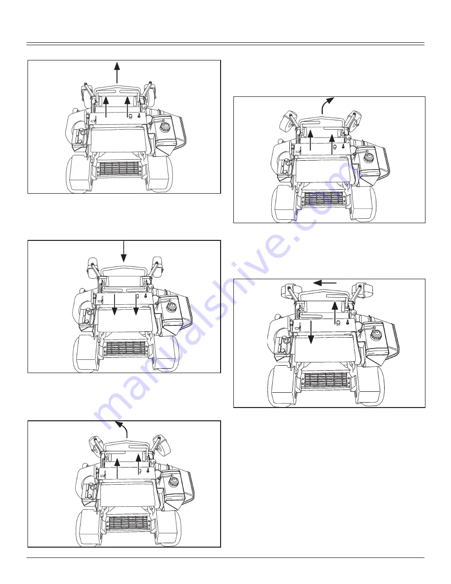
Forward:
Push both motion control levers forward at the same
time.
Reverse:
Pull both motion control levers past center rearward at
the same time.
Gentle Left Turn:
•
•
• Push right motion control lever further forward than the
left motion control lever
Gentle Right Turn:
• Push left motion control lever further forward than the right
motion control lever.
Sharp Left Turn:
• Push right motion control lever forward and pull left motion
control lever rearward at the same time.
Sharp Right Turn: