background image

GRAUPNER GmbH & Co. KG D-73230 KIRCHHEIM/TECK GERMANY


Keine  Haftung  für  Druckfehler.  Technische  Änderungen  vorbehalten!  Liability  for  printing  errors  excluded.  We  reserve  the  right  to  introduce  modifications.  Sous  réserve  de 
modifications! Nous ne sommes pas responsables d’éventuelles erreurs d’impression!         #0058129 


08/2007


18


• 

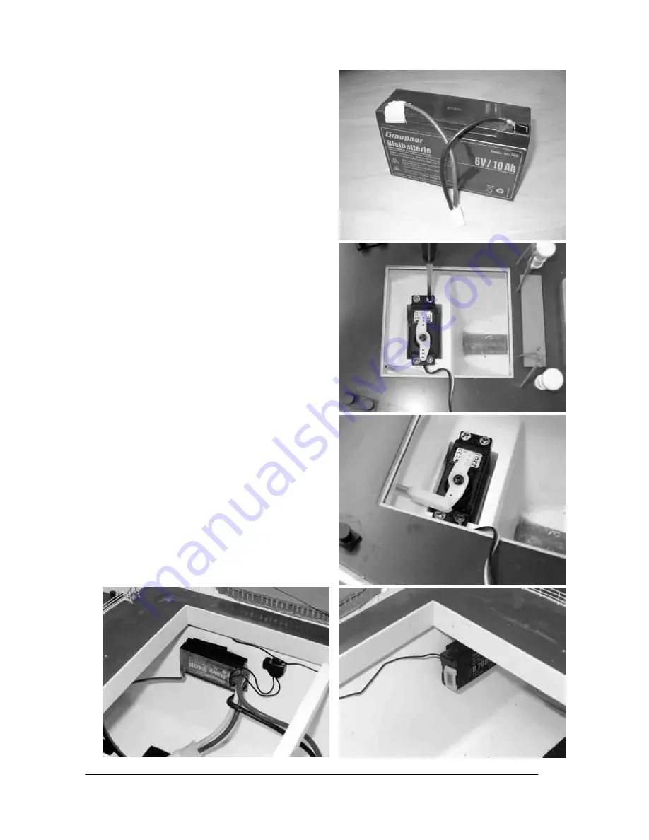
Cut a length of dual-core cable around 25 cm long 
and  solder  it  to  the  battery  terminals  at  one  end 
and  a  pair  of  G2  sockets  at  the  other. 

TIP:

  wrap 

insulating  tape  round  the  soldered  joints  at  the 
battery  terminals;  in  the  photograph  only  one  end 
is shown insulated. 

• 

Check  that  the  propeller  and  the  screws  in  the 
shaft coupling (arrow) are tight, as they may have 
come  loose  in  transit;  carefully  re-tighten  them  if 
necessary.  You  can  check  this  by  pulling  on  the 
propeller: if the shaft can be withdrawn to the rear, 
one of the grubscrews is loose. Remove the hatch 
and  fold  the  derricks  to  one  side  in  order  to  gain 
access  to  the  grubscrews,  then  tighten  them 
carefully. 

NOTE:

  if  the  grubscrews  are  loose, 

apply a drop of thread-lock fluid to them, e.g. UHU 
schraubensicher,  Order  No.  952,  as  vibration 
could  cause  them  to  work  loose  again  while  the 
boat is running. 

• 

Fit  the  double-ended  servo  output  lever  on  the 
rudder  servo.  Press  the  rubber  grommets 
(supplied with the servo) into the mounting lugs of 
the  rudder  servo,  and  push  the  brass  spacer 
sleeves  through  them  from  the  underside.  Fit  the 
servo in the opening in the internal hull, and drill 1 
mm  Ø  pilot-holes  through  the  mounting  lug  holes 
before  securing  the  servo  using  the  retaining 
screws  supplied. 

IMPORTANT:

  take  care  not  to 

damage the servo lead when you fit the screws. 

• 

Set the rudder servo to centre from the transmitter. 
Move  the  rudder  blade  to  the  “straight  ahead” 
position,  and  adjust  the  rudder  pushrod  in  such  a 
way that the clevis pin fits exactly in the hole in the 
servo output arm. 

• 

Attach  Velcro  (hook-and-loop)  tape  or  double-
sided  foam  tape  to  the  speed  controller  and  the 
receiver; install these components on the inside of 
the hull wall in the vicinity of the superstructure. 

• 

Connect the rudder servo and the speed controller 
to  the  receiver;  the  extension  lead  is  required  for 
the  rudder  servo.  Secure  the  cables  neatly  in  the 
hull using cable ties or Velcro tape. 


Summary of Contents for CAP SAN DIEGO 2011

Page 1: ...ertigen Fertigmodellen ist bisher in dieser Detaillierung auf dem Markt unerreicht Um diese hochwertige Ausf hrung zu erreichen ist der Rumpf aus stabilem GFK die Aufbauten und das Deck aus gelaserten...

Page 2: ...lb der Anspruchsfrist ordnungsgem geltend gemachten Anspruch aus dieser Erkl rung nicht anerkennen verj hren s mtliche Anspr che aus dieser Erkl rung in 6 Monaten vom Zeitpunkt der Geltendmachung an j...

Page 3: ...len wenn der Fahrakku nicht angeschlossen ist Bei angeschlossenem Fahrakku d rfen Sie und andere Personen niemals in den Bereich der drehenden Antriebsteile besonders der Schiffsschrauben kommen Die e...

Page 4: ...erden und mit wasserneutralem Fett z B Best Nr 570 neu abgeschmiert werden Montageanleitung Packen Sie das Modell und den Schiffsst nder vorsichtig aus Um das Modell ffnen zu k nnen merken Sie sich zu...

Page 5: ...Schaltplan auf Seite 10 ist rot ist schwarz Achten Sie auf die Drehrichtung des Motors wenn der Akku angeschlossen ist sollte die Schiffsschraube sich so drehen dass das Modell vorw rts fahren w rde...

Page 6: ...Ladeb ume zur Seite wegklappen um an die Madenschrauben zu kommen HINWEIS sichern Sie die evtl lockeren Madenschrauben mit Schraubensicherungslack z B UHU schraubensicher Best Nr 952 da diese sich du...

Page 7: ...Sie die Akkus in das Modell stecken diese an das Parallelkabel an und testen Sie die Funktionen der RC Anlage Die Akkus m ssen f r den Fahrbetrieb unbedingt fest fixiert werden damit sie nicht rutsch...

Page 8: ...Haftung f r Druckfehler Technische nderungen vorbehalten Liability for printing errors excluded We reserve the right to introduce modifications Sous r serve de modifications Nous ne sommes pas respons...

Page 9: ...Haftung f r Druckfehler Technische nderungen vorbehalten Liability for printing errors excluded We reserve the right to introduce modifications Sous r serve de modifications Nous ne sommes pas respons...

Page 10: ...modifications Nous ne sommes pas responsables d ventuelles erreurs d impression 0058129 08 2007 10 3061 Fahrtregler zum Empf nger Motor G2 Stecker G2 Stecker zum Fahrtregler 3061 Fahrakku Fahrakku 306...

Page 11: ...nell besitzt einen gro en Wendekreis und einen langen Bremsweg und sollte daher auf einem geeigneten gr eren Gew sser eingesetzt werden Fahren Sie auch nicht zu weit weg vom Ufer Viel Spa beim Fahren...

Page 12: ...orbehalten Liability for printing errors excluded We reserve the right to introduce modifications Sous r serve de modifications Nous ne sommes pas responsables d ventuelles erreurs d impression 005812...

Page 13: ...from laser cut ABS parts Many of the small items are of metal and almost everything is factory assembled The hull parts of the superstructure the masts and fittings are spray finished using semi matt...

Page 14: ...me of implementation however this cannot occur before the end of the claim period Applicable law This declaration and the claims rights and obligations arising from it are based exclusively on the per...

Page 15: ...keep well clear of the area around the propellers and make sure any spectators do the same Do not be tempted to exceed the recommended operating voltage Higher voltages may cause the motor or speed c...

Page 16: ...grease e g Order No 570 Assembling the model Carefully unpack the model and the boatstand The first step is cautiously to lift off the superstructure to open the deck so that the receiving system can...

Page 17: ...e wiring diagram on page 10 is red is black Ensure that the motor spins in the correct direction when the batteries are connected the propeller should rotate in such a way that the model would be prop...

Page 18: ...ly a drop of thread lock fluid to them e g UHU schraubensicher Order No 952 as vibration could cause them to work loose again while the boat is running Fit the double ended servo output lever on the r...

Page 19: ...allel battery lead Order No 3061 to the speed controller Place the batteries in the model connect them to the parallel lead and check the working systems The batteries must be fixed securely so that t...

Page 20: ...aftung f r Druckfehler Technische nderungen vorbehalten Liability for printing errors excluded We reserve the right to introduce modifications Sous r serve de modifications Nous ne sommes pas responsa...

Page 21: ...aftung f r Druckfehler Technische nderungen vorbehalten Liability for printing errors excluded We reserve the right to introduce modifications Sous r serve de modifications Nous ne sommes pas responsa...

Page 22: ...entuelles erreurs d impression 0058129 08 2007 22 3061 Speed controller To receiver Motor G2 plug G2 plug To speed controller 3061 Drive battery 3061 3061 3061 With two drive batteries and supplementa...

Page 23: ...wn it therefore needs to be operated on a large stretch of water Don t allow the boat to travel too far away from the bank We hope you have many hours of pleasure running your model of the Cap San Die...

Page 24: ...n Liability for printing errors excluded We reserve the right to introduce modifications Sous r serve de modifications Nous ne sommes pas responsables d ventuelles erreurs d impression 0058129 08 2007...

Page 25: ...d accastillage sont peints au pistolet avec des peintures satin es et la d coration est pos e Gr ce ces nombreux d tails et aux pi ces d accastillage le mod le une allure particuli rement r aliste Le...

Page 26: ...nt qu elle n y a pas t contrainte par le l gislateur la responsabilit de la Firme GRAUPNER n est aucunement engag e pour les d dommagements incluant les d g ts personnels les cas de d c s la d t riora...

Page 27: ...mp de rotation des h lices car il existe dans cette zone un s rieux danger de blessure Ne d passez pas la tension d alimentation conseill e Une tension trop lev e peut faire surchauffer les moteurs ou...

Page 28: ...usement le mod le et le support du bateau Pour pouvoir ouvrir le mod le rep rez d abord la position de chaque m t de charge avec les tais accrochez ensuite soigneusement ceux ci et tournez les m ts de...

Page 29: ...le moteur R f rez vous au sch ma de c blage sur la page 10 est rouge est noir Veillez au bon sens de rotation du moteur lorsque les accus sont connect s l h lice en tournant doit propulser le mod le e...

Page 30: ...pouvoir y acc der NOTE Bloquer les vis pointeau qui se sont ventuellement desserr es avec du freine filet Par ex UHU R f N 952 car celles ci pourraient nouveau se desserrer par les vibrations durant...

Page 31: ...61 sur le r gulateur de vitesse Placez les accus dans le mod le reliez les au cordon parall le et testez les fonctions de l installation R C Les accus devront tre bien fix s durant la navigation afin...

Page 32: ...aftung f r Druckfehler Technische nderungen vorbehalten Liability for printing errors excluded We reserve the right to introduce modifications Sous r serve de modifications Nous ne sommes pas responsa...

Page 33: ...aftung f r Druckfehler Technische nderungen vorbehalten Liability for printing errors excluded We reserve the right to introduce modifications Sous r serve de modifications Nous ne sommes pas responsa...

Page 34: ...urs d impression 0058129 08 2007 34 Sch ma de c blage Vers le r cepteur 3061 R gulateur de vitesse Moteur Connecteur m le G2 Vers le r gulateur de vitesse 3061 Accu de propulsion 3061 3061 3061 Avec 2...

Page 35: ...tissement c est pourquoi il devra tre utilis sur un plan d eau d une surface adapt e Ne vous loignez pas non plus trop loin de la rive Nous souhaitons beaucoup de plaisir avec la navigation de votre m...

Page 36: ...en Liability for printing errors excluded We reserve the right to introduce modifications Sous r serve de modifications Nous ne sommes pas responsables d ventuelles erreurs d impression 0058129 08 200...

Reviews: