GRAUPNER GmbH & Co. KG D-73230 KIRCHHEIM/TECK GERMANY
Änderungen vorbehalten! Keine Haftung für Druckfehler!
Id.-Nr. 0058032 01/2008 24
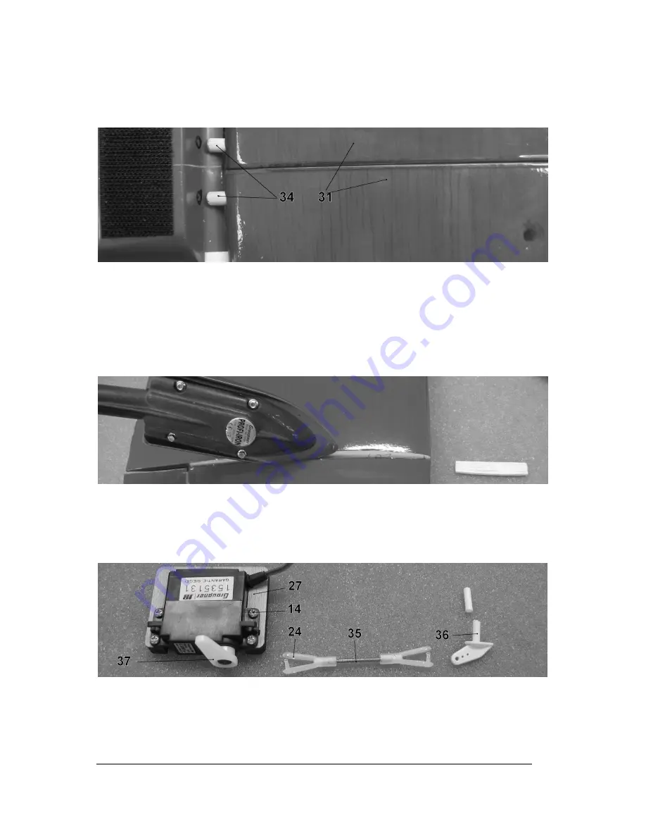
Fit the wing panels (31) together using the steel joiners rods (32) and (33). Round off the ends of the
hardwood dowels (34) and glue them in the holes in the wing root leading edge. Cut away the
covering film over the aileron lead exit holes and run the extension leads out of the openings.
Remove the covering film over the aileron servo recesses in the outboard wing panels.
Place the wing on the fuselage, set it central, and mark the position of the holes for the locating
dowels; drill the holes 5 mm Ø.
Place the wing on the fuselage and position it accurately. Mark the position of the holes in the wings
on the fuselage cross-piece, and drill them 5 mm Ø, using the wing itself as a drilling template.
Remove the wing again and open up the holes in the plywood cross-piece to 7 mm Ø in order to
accept the captive nuts (39). Sand the outside of the captive nuts (39) and glue them in the underside
of the cross-piece (9). Tip: a good method is to fit the screws (40) from above, and tighten them to
draw the nuts upwards into the cross-piece.
Slit the covering film along the centre of the dihedral joint on the top of each wing panel, remove the
packing strip, and iron the projecting strips of film down onto the facing ribs using a film iron, Order No.
1226. Apply glue to the joint surfaces, and pack up the outboard panels by the same amount on each
side, so that the facing ribs meet snugly in the centre. Allow the glue to set hard, then apply the
reinforcing strips (1) to the top and bottom of the dihedral joints.
Fit the aileron servos in the wing recesses, and secure them using the self-tapping screws (14).
Assemble the aileron pushrods from parts (24) and (35). Remove the head from the screws (35) using
side-cutters. Fit the output levers (37) on the aileron servos: note that they should be offset slightly
forward of centre when the servos are at neutral. Shorten the aileron horns (36) and drill out the
linkage holes to 1.6 mm Ø.


