


11
Kula
Installation Manual
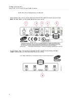
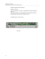
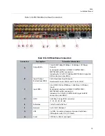
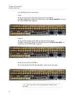
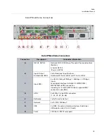
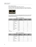
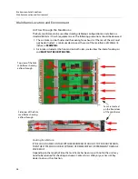
Kula Mainframe Rear Connectors
The table below outlines a 2M/E mainframe.
A
G
F
B C
D
E
H
Kula Mainframe Connectors
Connectors
Description
Connector Information
A
Output BNCs
12x SDO BNC Outputs total (numbered BNC 1 to 12)
(6x SDO BNC Outputs on the 1M/E Mainframe)
B
Input/Output
Bi-directional BNCs
4x SDI/SDO BNC Inputs plus 2x Bi-Directional
Input/Outputs.
Numbered: 37 to 42 (2M/E) and 13 to 18 (1M/E)
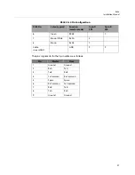
C
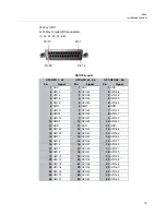
GPIO
3x 25 Way D-type GPIO connectors
(1 - 22, 23 - 44, 45 - 66)
D
Reference
1x Ref In and 1x Ref out
E
Network
3x 10/100/1000 base T
F
USB
2x USB3 - for external memory device or hard drives
USB outputs are 5 V DC, 0.9 A each
G
Serial
2X RJ45, RS422 Ethernet ports
H
Inputs
36x SDI BNC (numbered BNC 1 to 36)
(18x SDI BNC Inputs on the 1M/E Mainframe)
Note:
Inputs and Outputs will vary, depending on the Kula system
purchased.
Summary of Contents for KULA
Page 1: ...Installation Manual Issue 5 Rev 1 2020 10 29 KULA PRODUCTION SWITCHER ...
Page 16: ...xvi Notices ...
Page 20: ...2 Introduction About this Manual ...
Page 40: ...22 Cabling and Connections Mainframe Connections ...
Page 50: ...32 Environment and Location Ancillary Panels ...
Page 61: ...43 Kula Installation Manual Desk Cutout Dimensions for K5P 1M E 19 Control Surface ...


