22
8935CF — Instruction Manual
Installation
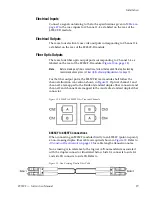
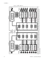
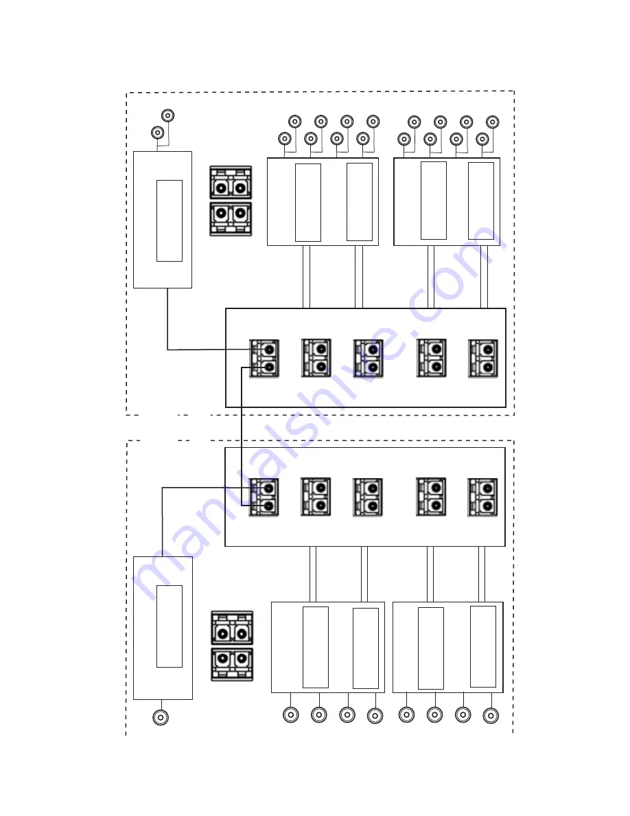
Figure 15. CWDM Configuration
8543_10
8939FCA
8935CF
Fiber Out 1
to 1610nm
Fiber In 1
from 1610nm
Fiber In 2
from 1590nm
Fiber In 3
from 1570nm
Fiber In 4
from 1550nm
Fiber Out 3
to 1570nm
Fiber Out 4
to 1550nm
Fiber Out 2
to 1590nm
Fiber Out 1
to 1530nm
Fiber Out 3
to 1490nm
Fiber Out 4
to 1470nm
Fiber Out 2
to 1510nm
Electr
ical
Inputs
Multiple
x
e
r
Dem
ultiple
x
e
r
T
op Submodule
Bottom Submodule
8935CF
SFP-CWDM-3
1550nm & 1570nm
Fiber In 1
from 1530nm
Fiber In 2
from 1510nm
Fiber In 3
from 1490nm
Fiber In 4
from 1470nm
T
op Submodule
SFP-CWDM-4
1590nm & 1610nm
Bottom Submodule
SFP-CWDM-1
1470nm & 1490nm
SFP-CWDM-2
1510nm & 1530nm
8935FC
T
o
p Submodule
Bottom Submodule
SFP-DRX-1
1270 > 1610nm
T
o
p Submodule
SFP-DRX-1
1270 > 1610nm
Bottom Submodule
SFP-DRX-1
1270 > 1610nm
SFP DRX-1
1270 > 1610nm
COM
EXP
CH1
1470nm
CH2
1490nm
CH4
1530nm
CH3
1510nm
CH4
1570nm
CH5
1550nm
CH8
1610nm
CH7
1590nm
8939FCA
COM
EXP
CH1
1470nm
CH2
1490nm
CH4
1530nm
CH3
1510nm
CH4
1570nm
CH5
1550nm
CH8
1610nm
CH7
1590nm
8935FC
Electr
ical
Outputs
Location A
Location B
8935FC Fiber Inputs
1
2
4
3
IN
IN
8935CF Fiber Outputs
1
2
4
3
OUT
OUT
Gec
k
oFle
x Fiber-Ready Module
1310-DTL
Submodule
Gec
k
oFle
x Fiber-Ready Module
1310-DRL
Submodule
Ch 1
Ch 2
Ch 3
Ch 4
Ch 1
Ch 2
Ch 3
Ch 4
Coax In
Fiber Out
Ch 1
Coax
Ouputs
Ch 3
Ch 4
Ch 2
Ch 1
Ch 2
Ch 3
Ch 4
Ch 1
Ch 3
Ch 4
Ch 2
Ch 1
Ch 2
Ch 3
Ch 4
Note:
In this configur
ation (8959CF
A to 8939CF
A utilizing CWDM tr
ansmitters), if the distance betw
een 8939CF
A modules is l
ess than 12 km (7.5 m),
a 3 dB atten
uator m
ust be installed some
where betw
een the COM por
ts on the 8939CF
A modules to pre
v
e
nt o
v
erdr
iving the receiv
er
causing bit errors
to occur on the link.
*
Distance of
up to 50km
( see note
for inline
atten
uation
requirements)
*

