8935CF — Instruction Manual
15
Installation
Channel 1 and Channel 2 Submodule and Fiber Cable Installation
On the top side of the module, install the submodule you wish to use for
the Channel 1 and Channel 2 outputs as follows:
1.
Remove the black rubber dust cover from the SMV_SFP submodule.
2.
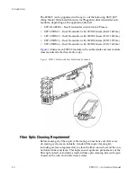
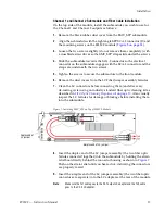
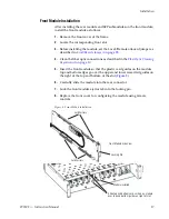
Align the submodule with the right angle SFP SCA-2 connector (J1) and
the mounting screws on the 8935CF module (
3.
Loosen the two screws slightly (do not remove them completely) with
a crossblade screwdriver so the SMV_SFP straps slide under the screws.
4.
Slide the submodule towards the SCA-2 connector so the electrical
connector on the submodule engages with the SCA-2 connector and the
straps are underneath the two screws.
5.
Tighten the screws to secure the submodule to the front module.
6.
Remove the dust covers from the LC Fiber Jumper assembly ferrules.
7.
Clean the LC connectors before connecting them (and after every
de-mating cycle) using an industry standard fiber optic cleaning kit as
described in
Fiber Optic Cleaning Requirement
. Also visually
inspect the LC ferrules for damage or blockage before installing them
into the submodule.
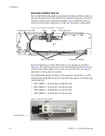
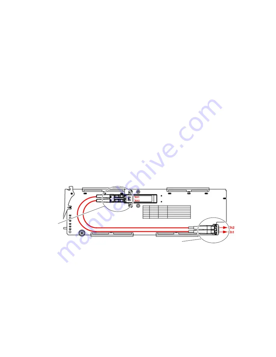
Figure 7. Installing SMV_SFP on Top of 8935CF Module
8.
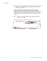
Insert the duplex end of the LC jumper assembly (the two fiber optic
ferrules connected together) into the submodule by holding the strain
relief boot directly behind the connector housing as shown in
.
Push on the strain relief until you hear a click, indicating the connectors
are properly mated.
9.
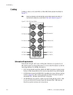
Insert the simplex end of the LC jumper assembly (the two fiber optic
connectors are separate) into the LC adapters at the rear of the module.
Note
Make sure the Tx1 cable goes to the Ch 1 output LC adapter and the Tx2 cable
goes to the Ch 2 LC adapter.
Duplex end of
LC jumper
Simplex end of LC jumper


