


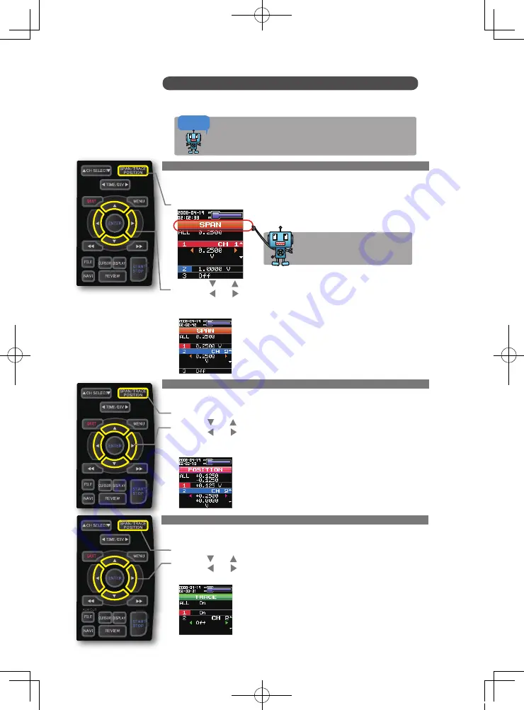
1. How to Make a Span setting.
The Span parameter is used to adjust the amplitude of the input waveform.
This setting is made in the aforementioned Free Running status.
(1) Adjust the span display width for CH 2 to 0.25V.
(2) Press the SPAN/POSITION/TRACE key to select the SPAN mode.
(3) Use the and keys to make CH 1 active (enlarged display).
(4) Use the and keys to change the Span value. Here we will set the value to 0.25V.
When this setting has been made, the waveform screen scale will be set to "+0.125
to -0.125".
2. How to make a Position setting.
The Position parameter is used to adjust the zero position's upper and lower positions
for the input waveform.
(1)Press the SPAN/POSITION/TRACE key to select the POSITION mode.
(2)Use the and keys to make CH 1 active (enlarged display).
(3)Use the and keys to set the Position value to "+0.25V to –0V".
When this setting has been made, the waveform screen scale will be set to "+0.25V
to -0V".
3. How to make a Trace setting.
The Trace parameter can be used to specify the waveform display of selected channels
as On or Off.
(1)Press the SPAN/POSITION/TRACE key to select the TRACE mode.
(2)Use the and keys to make CH 2 active (enlarged display).
(3)Use the and keys to select Off.
When this setting has been made, the CH 2 waveform is not displayed.
Span, Position and Trace Functions to Adjust the Waveform Display
Points to
Remember !
17
These functions enable you to make adjustments in order to view individual
channels more easily, and to delete waveforms that you do not need to view.
The span, position and trace operations can be performed while the
GL900 is in the Free Running status, while it capturing data, and while
it is replaying data. The changes made are applied to the displayed
data only, and so the original data is not affected in any way.
The currently selected mode (SPAN,
POSITION or TRACE) can be checked
by looking at the "Waveform Operation
Display Area".
GL900-Quick-E.indd 18
08.5.15 3:27:54 PM


