SETUP MANUAL
This manual provides the setup procedure. For details on
each function, refer to the instruction manual (PDF) .
The manual (PDF) is available at:
http://www.graphteccorp.com/support/index.html
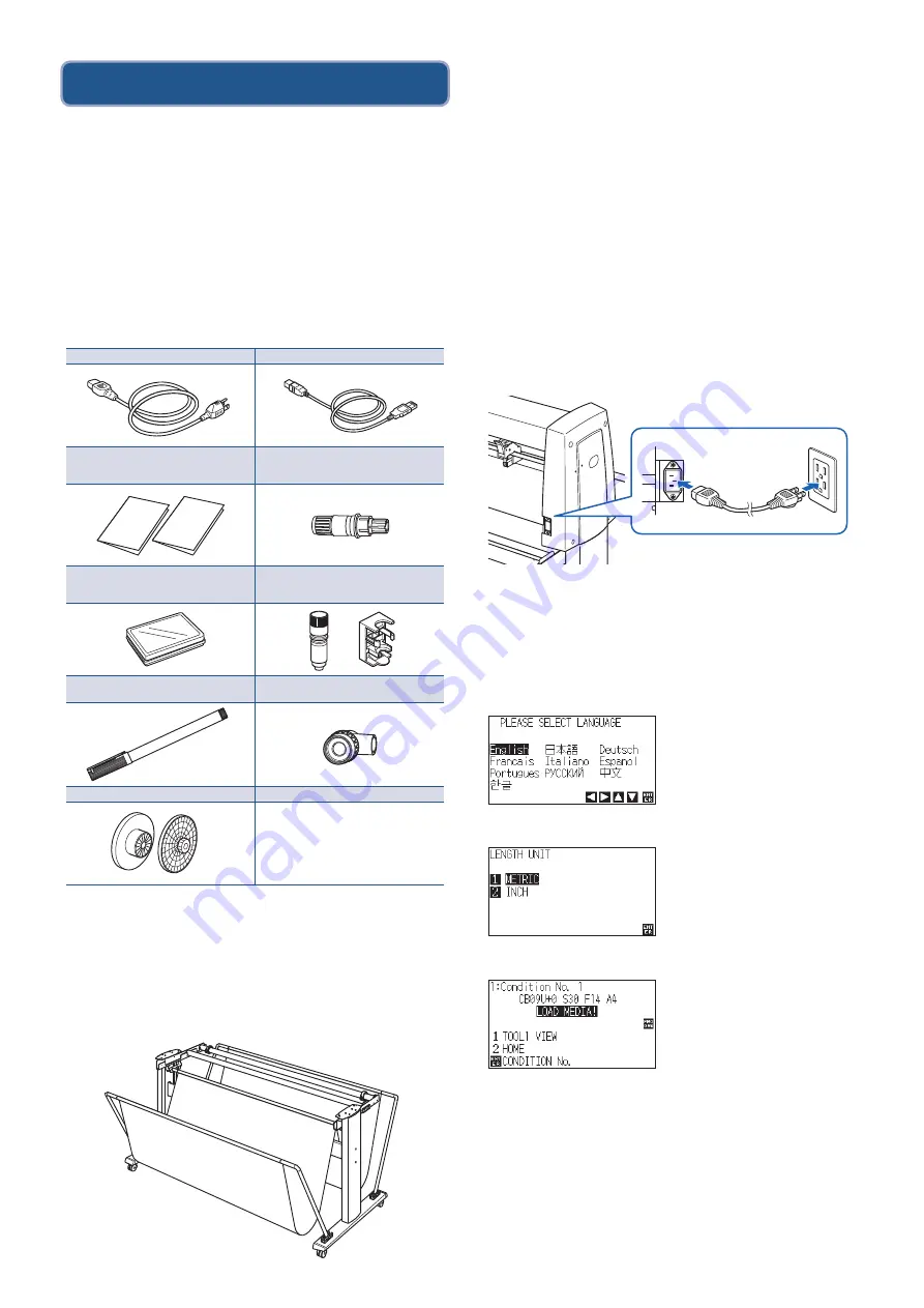
Checking the Accessories
Please check that all the accessories are complete. If you
find any accessories missing, please contact the distributor
where you purchased or our customer center immediately.
Accessories
* In addition, various information may be attached.
* Accessories may vary depending on the sales area.
* For details, please contact the distributor where you purchased.
Dedicated accessories
A stand (with a basket) is supplied.
* Dedicated accessories may be different.
Installing driver/software
The latest driver / software version and installation
instructions are available at:
http://www.graphteccorp.com/support/index.html
Please download it if necessary.
•
Windows driver (Do not connect the computer to the cutting
plotter before installing.)
•
Graphtec Studio 2 (Windows/Mac)
•
Cutting Master 5 (Windows/Mac)
Connecting to the Power
Make sure that the power switch is off (O side), and make a
connection between the power connector of the cutting
plotter and the AC outlet of specified voltage using the
supplied power cable.
Initial setup screen
The initial setup screen is displayed only when the power is
first turned on. Then select "DISPLAY LANGUAGE" and
"LENGTH UNIT". When the power switch is turned on
(I side), a message is displayed after displaying the version.
Select a language (English) and press the [ENTER] key.
Select the length unit and press the [ENTER] key.
It will return to default screen.
SETUP MANUAL,
TO ENSURE SAFE AND CORRECT USE
1 of each
Cutter plunger (PHP33-CB09N-HS)
1 pc.
Cutter blades (CB09UB [1P])
1 pc. Water-based fiber pen adapter
(PHP31-FIBER)
(Plunger/Height adjustment tool.) 1 set
Water-based fiber pen (KF700-BK [1P])
1 pc.
Cutter blade adjustment magnifier
(PM-CT-001)
1 pc.
Flange set (OPH-A21)
1 set
Power cable
1 pc. USB cable
1 pc.
Summary of Contents for FC9000 Series
Page 2: ......
Page 13: ...3 3 160mm USB RS 232C 3 2 MENU ADV LAN USB RS 232C 9 9 GOOD NG 3 3...
Page 14: ...COND TEST 1 2 1 2 3 4...
Page 16: ...3 3 160mm USB RS 232C 3 2 MENU ADV LAN USB RS 232C 9 9 GOOD NG 3 3...
Page 17: ...COND TEST 1 2 1 2 3 4...
Page 19: ...160 USB RS 232C MENU LAN USB RS 232C 9 9 GOOD NG...


