Grantec Electronic Grand PC2TV WIRELESS Manual Download Page 8

CHAPTER 4 

CHAPTER 3 

TECHNICAL SPECIFICATIONS 

TECHNICAL TIPS 


4.1 Transmitter 

The following are problems that might arise when using the Grand PC2TV converter, and 

possible solutions to them. 

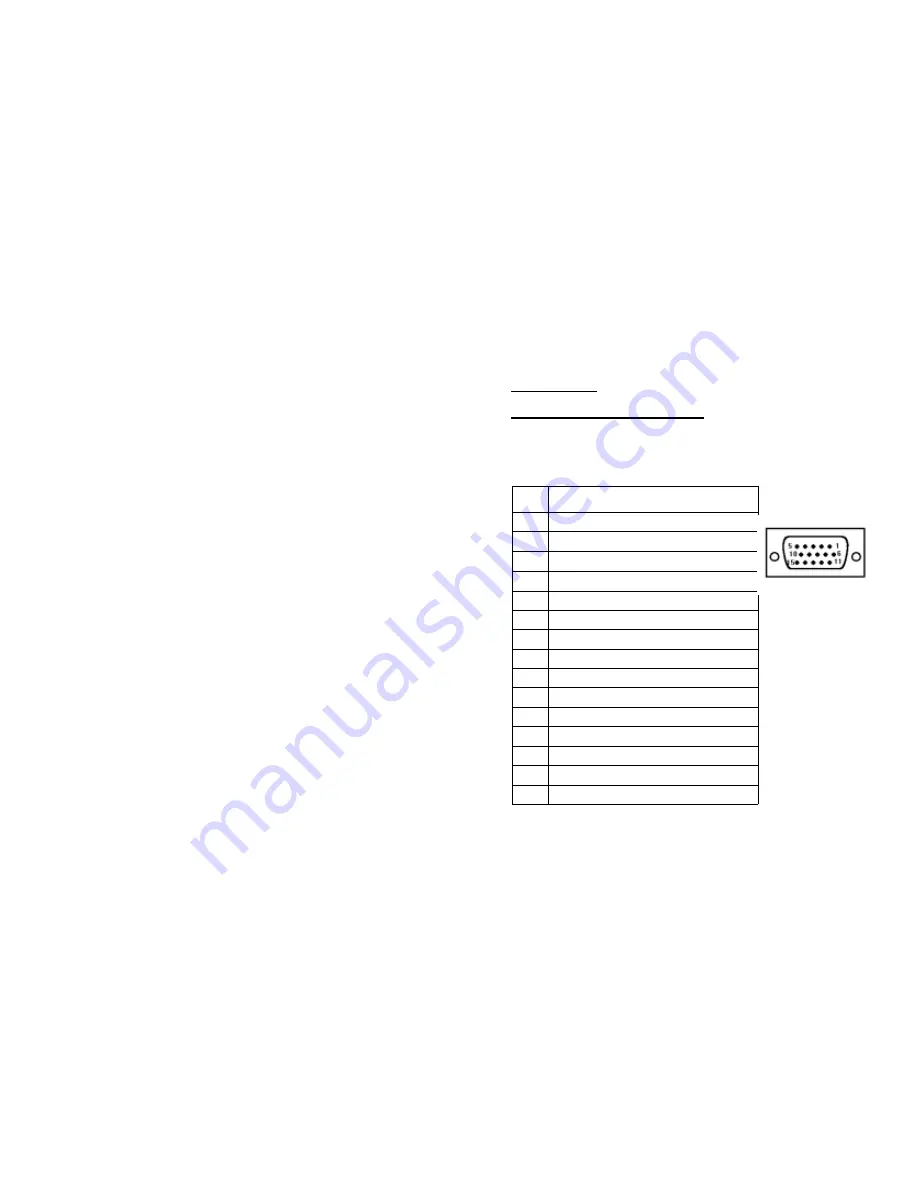
4.1.1 SCAN CNVTR CONNECTOR 


Analog RGB and SYNC signal from 15 pin VGA output port of PC or Notebook PC, and 

output SYNC signal to monitor. 

Q: How can I enhance the display quality? 


A:  

You can usually decrease the contrast and increase brightness control to get 

Pin No. 

Signal Description 

RED IN, 0.7Vpp 

±

 0.1Vpp, 75 ohms, from PC 

GREEN IN, 0.7Vpp 

±

 0.1Vpp, 75 ohms, from PC 

BLUE IN, 0.7Vpp 

±

 0.1Vpp, 75 ohms, from PC 

HSYNC IN, TTL level 

VSYNC IN, TTL level 


Ground


NC


Ground


Ground

10 


Ground

11 

RED out, 0.7Vpp 

±

 0.1Vpp, 75 ohms, To Monitor 

12 

GREEN out, 0.7Vpp 

±

 0.1Vpp, 75 ohms, To Monitor 

13 

BLUE out, 0.7Vpp 

±

 0.1Vpp, 75 ohms, To Monitor 

14 

HSYNC  OUT, TTL level 

15 

VSYNC  OUT, TTL level 


the better picture (ON TV).   


Q: I connect with a NOTEBOOK PC, no output is displayed on TV. 

A:

 Please refer to your computer’s User’s Manual to display an external VGA Signal. 

(Many Notebook computers have 3 settings, VGA external only, VGA internal only, and 

VGA internal & external simultaneously) 


Remark: Case is connected to ground

 15 

 16 

Summary of Contents for Grand PC2TV WIRELESS

Page 1: ...terference received including interference that maycause undesired operation Federal Communications Radio Frequency Interference Statement Note This equipment has been tested and found to comply with the limits for a Class B digital device Pursuant to part 15 of the FCC Rules These limits are designed to provide reasonable protection against harmful interference when the equipment is operated in a...

Page 2: ... GRAND PC 2 TV WIRELESS 1 1 INTRODUCTION Thank you for purchasing the Grand PC2TV WIRELESS GRAND PC2TV WIRELESS is a VGA to TV converter with an integrated 2 4GHz Wireless Transmitter separate Receiver Transmit the computer s video and audio to any remote TV It is ideal for Internet or DVD VCD movie viewing presentations baby patient monitoring burglary detection theft prevention or home company m...

Page 3: ...68 Vertical frequency Hz 117 95 75 Frequency Generating P L L Audio Response 20Hz 20kHz Video Output 1Vpp 75 ohm composite Video 1 4 SYSTEM REQUIREMENTS Distance Open area is 100 meters indoor is 30 meters Actual range may vary depending on environment Desktop or laptop computer with HD15 VGA standard connection TV or VCR that supports NTSC or PAL video standard with composite video input required...

Page 4: ...IRELESS Refer to Figure 1 for the Outline of Grand ULTIMATE WIRELESS Power adapter DC 6V 800mA For Rx Grand PC2TV WIRELESS Rx Audio Video Cable for Rx Video SCART cable with Audio for Europe Power adapter DC 6V 800mA S Video cable Video cable Audio cable Y cable for IBM PC Audio Video Cable Video SCART cable with Audio FIG 1 Outline of Grand PC2TV WIRELESS 7 8 ...

Page 5: ... SIZE Press the button to select the current display size FREEZE Toggle between freeze and normal display When is FREEZE mode the ZOOM LED is flash ZOOM Toggle between Zoom and Normal display for converted computer display When is ZOOM mode the ZOOM LED is light PAL NTSC Press this button to select PAL or NTSC When is PAL mode the PAL LED is light 10 POSITION Press up down left and right button to...

Page 6: ... port on the back of your laptop or desktop PC On a desktop you may need to first unplug the monitor ig 3 Laptop Connection Fig 4 Desktop with Monitor Connect one end of the audio pass through cable to the AUDIO IN port on the Fig 5 Audio Pass Through Cable F 3 Grand PC2TV Wireless Connect the other end to the LINE OUT or SPEAKER OUT of your sound card On a desktop you may first have to disconnect...

Page 7: ... may need to refer to your TV s user s manual for further assistance 7 If you are experiencing any distortion or interference in the change the transmission channels Using a paperclip change the switches on both the transmitter and the receiver so that they are on the same channel Only one switch should be DOWN on each and the switch that is DOWN indicates which channel is in use 8 If your TV does...

Page 8: ...1Vpp 75 ohms from PC 2 GREEN IN 0 7Vpp 0 1Vpp 75 ohms from PC 3 BLUE IN 0 7Vpp 0 1Vpp 75 ohms from PC 4 HSYNC IN TTL level 5 VSYNC IN TTL level 6 Ground 7 NC 8 Ground 9 Ground 10 Ground 11 RED out 0 7Vpp 0 1Vpp 75 ohms To Monitor 12 GREEN out 0 7Vpp 0 1Vpp 75 ohms To Monitor 13 BLUE out 0 7Vpp 0 1Vpp 75 ohms To Monitor 14 HSYNC OUT TTL level 15 VSYNC OUT TTL level the better picture ON TV Q I conn...

Page 9: ...C 5 No connection 6 No connection 7 Red output 0 7Vpp 75 ohms 8 Audio output left channel 1 Vrms 9 Audio output Right channel 1 Vrms 4 1 5 AUDIO IN CONNECTOR Connect to computer audio output line out or DVD VCR VCD audio output Input with 1Vrms max 4 1 6 VIDEO IN CONNECTOR Composite video input from DVD VCR VCD or security camera Input level 1 Vpp Remark Case is connected to ground 4 2 Receiver 4 ...

Page 10: ...KHz to KHz Vertical Freq Hz to Hz Problem description Check the following before requesting service Symptom Point to check No TV output Press the video select or AV button of the TV to select the video Input from the Grand PC2TV WIRELESS Text not sharp Use S Video or SCART connection Missing characters Set the Grand PC2TV WIRELESS to underscan Adjustment UP DOWN LEFT RIGHT position button to the c...

Reviews: