Grant spira User Instructions Download Page 8

8

6  Pellet Feed Tube 

Thermostat

This is a built-in safety device, mounted on 
the pellet feed tube (on the top of the burner) 
to automatically shut down the burner if the 
temperature on the pellet feed tube (between 
the pellet auger and the burner) exceeds a 
safe level. 

If this device should operate, it can be 
manually reset once the boiler and pellet feed 
tube has cooled down. 
To reset: 

• 

Isolate the electrical supply to the boiler 
(set the switch on the fused spur to off).

• 

Remove the red burner cover by 
loosening the four M5 screws (two on 
each side of the cover) and lifting it off 
the burner. The thermostat is located on 
the pellet feed tube. Refer to Figure 6-1.

• 

Disconnect the lead from the thermostat 
terminals. Refer to Figure 6-2.

• 

Press the reset button located between 
the two terminals. 

• 

Reconnect the lead. Ensure it is fully 
pushed on to thermostat terminals.

• 

Finally, refit the burner cover and tighten 
the four screws.

• 

Reconnect the electrical supply to the 
boiler and check operation.

NOTE

There is no power present on the two 
thermostat terminals when the lead has 
been disconnected, so there is no risk of 
electrocution when resetting the thermostat.

Figure 6-1: Location of pellet feed tube 
thermostat

Figure 6-2: Disconnect lead from pellet tube 
thermostat

7  Priming the 

Auger

The pellet feed auger on the pellet hopper 
MUST be fully primed BEFORE attempting 
to start the boiler. The auger should be 
initially primed by the Installer as part of the 
commissioning process.

If for any reason the auger needs to be re-
primed, this is a simple process using the 
following procedure:

Step 1

First set the burner ON/STANDBY switch to 
the STANDBY position.

Step 2

Disconnect the pellet feed auger 6-way plug 
(3) from the upper socket on the left side of 
the burner. Refer to Figure 7-1.

Figure 7-1: Remove plug 3 from burner

Step 3

Disconnect the 7-way plug (1) from  


the socket on the left side of the  


burner.Refer to Figure 7-2.

Figure 7-2: Remove plug 1 from burner

Step 4

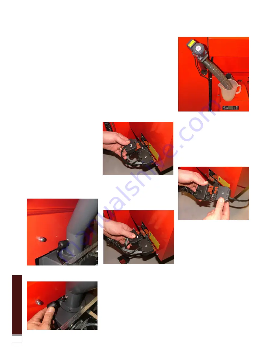
Disconnect the pellet delivery hose from the 
pellet feed tube (on the burner) and place the 
open end into a DRY container of at least 1 
litre capacity. Refer to Figure 7-3.

Figure 7-3: Pellet tube ready for priming the
pellet auger

Step 5

Insert the 6-way plug (3) into the 7-way plug 
(1). Refer to Figure 7-4. It is not possible to 
connect these two plugs incorrectly as they 
will only fit together one way. When these 
plugs are connected the pellet feed auger will 
run continuously.

Figure 7-4: Connect plugs together

Step 6

Leave the auger running until there is a 
continuous flow of pellets from the pellet 
delivery hose. This may take 15 to 20 
minutes. The pellet feed auger is now fully 
primed.

Step 7

Disconnect the two plugs from each other 
and the auger will stop.
Refit the pellet delivery hose onto the pellet 
feed tube of the burner.

WARNING
Ensure that the pellet delivery hose 
forms an air tight seal each end and that 
the hose is not damaged. Leakage of
air could cause increased temperature 
in the pellet delivery hose and result in 
the pellet feed tube thermostat shutting 
down the burner.

Summary of Contents for spira

Page 1: ...Part No DOC45 Rev00 October 2014 Grant Spira 6 26kW and 9 36kW Condensing Wood Pellet Boiler User Instructions...

Page 2: ...0 Emptying the Ash Pan 12 11 Cleaning and Servicing 14 your Boiler 12 Ventilation 14 13 Electricity Supply 14 14 Sealed Central Heating system 14 15 Frost Protection 14 16 Corrosion and Protection 14...

Page 3: ...de the boiler Figure 2 1 Contents switch in the base of the pellet hopper When there is no bulk store but the pellet hopper only the contents switch stops the burner operating when the minimum pellet...

Page 4: ...ed with a self cleaning system to keep the heat exchanger tubes clear of ash build up As with the brazier cleaning system these are operated automatically after a pre set period has elapsed CAUTION Ev...

Page 5: ...installer or Grant service engineer to manually operate and test the automatic cleaning systems in both heat exchangers When released it will automatically return to the default AUTO position to allo...

Page 6: ...operate 5 C below the set point the boiler is in 100 power mode 5 C above the set point the boiler has reached minimum output The set point is NOT the temperature at which the burner stops The maximum...

Page 7: ...r Messages The burner control panel display can also indicate that a fault has occurred with the boiler In the event of a fault one of the following error fault messages may be seen scrolling across t...

Page 8: ...Installer as part of the commissioning process If for any reason the auger needs to be re primed this is a simple process using the following procedure Step 1 First set the burner ON STANDBY switch to...

Page 9: ...ay Refer to Section 5 4 Active Symbols Set the burner ON STANDBY switch to ON The flue fan will start and pellets will be delivered to the burner for it to start NOTE If the burner ON STANDBY switch i...

Page 10: ...rammer room thermostat etc calling for heat If not set controls to call for heat If after checking the above there is still a problem then contact your Installer for assistance STEP 4 Which one of the...

Page 11: ...olling across the bottom of the burner control panel display Check the following Are the three plugs correctly fitted to the left side of the burner Press the RESET button on burner control panel to c...

Page 12: ...the procedure below Step 1 Set the burner STANDBY ON switch to STANDBY Step 2 If the boiler is running at the time wait for it to complete the burner shut down sequence i e until the burner control pa...

Page 13: ...both of the carrying handles one at the front and the other at the back carefully lift the ash pan out of the boiler Refer to Figure 10 7 Do NOT use the centre cross bar of the ash pan as a carrying...

Page 14: ...d with your programmer for further details It is recommended that you check that the on off and time settings after a power failure has occurred WARNING The electricity connections to the boiler must...

Page 15: ...heck Primary heat exchanger inspect clean Secondary heat exchanger inspect clean Wash system inspect clean Combustion chamber inspect clean Fan inspect clean Shaker mechanism grease Shaker system chec...

Page 16: ...GRANT ENGINEERING UK LIMITED Hopton House Hopton Industrial Estate Devizes Wiltshire SN10 2EU Telephone 01380 736920 Fax 01380 736991 Email info grantuk com Website www grantuk com...

Reviews: