background image

7. Pump specifications

7.1

Pumps come as part of the GD120, GR150 and GP200 thermostats. For details on their
operation please refer to the appropriate operating instructions (as supplied with the
units):

GD120………………………..Part No.17090
GR159, GP200………………Part No.17091

If greater head (pressure) is required you can choose from two accessory pumps and the
appropriate pump lid.

(head 10m/flow 9 litres/ min.).............................240V 50Hz
(head 17m/flow 12 litres/ min.)...........................

Pump lid for R1/L, R2/L, R3/L
Pump lid for R4/L
Pump lid for R5

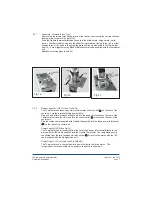
Pump attached to lid with four screws

supplied.

Pump Lid ( R1/L, R2/L, R3/L version

shown).

Pump-output tube with internal bore

suitable to fit 12.7mm diameter pump
output. Secured with retaining clip.

Pump-return tube with internal bore

suitable to fit 12.7mm diameter pump
return. Secured with retaining clip.
The Pump and Lid assembly can
now be attached to the Refrigeration unit
using the two knobs supplied. The tubes
can now be attached to the required
equipment or apparatus.

VTP1
VTP2

Pumps

240V 50Hz

(head 10m/flow 9 litres/ min.)...........................110V 60Hz
(head 17m/flow 12 litres/ min.).........................110V 60Hz

VTP1L
VTP2L

4

1

3

Fig 5 Pump in position

Page19

Version 4 - Jan 2010

Low temperature bath/circulator
Operating instructions

1

2

3

4

Summary of Contents for R Series

Page 1: ...Operating instructions Low temperature bath circulator R series ...

Page 2: ...Page 2 Low temperature bath circulator Operating instructions Version 3 May 2005 ...

Page 3: ...ference and description 3 3 Thermostat unit 3 4 Filling 3 5 Switching ON and setting up 4 Specific examples 12 5 Fault diagnosis 15 6 Technical specification 17 7 Pump specifications 19 8 Maintenance 21 9 Guarantee and service 22 7 1 Cleaning 7 2 Replacement of fuses Page 3 Low temperature bath circulator Operating instructions Version 4 Jan 2010 ...

Page 4: ...h and isolating device power supply connector are easily accessible during use Connect only to a power supply which provides a safety earth ground terminal Before moving disconnect at the power supply socket Do not touch surfaces which become hot during high temperature operation Ensure that the operating temperature is less than the maximum operating temperature of your sample material Do not blo...

Page 5: ...draining allow the liquid to cool to below 50 C Use only liquids specified in the operating instructions within the specified temperature range If the alarm lamp is illuminated the liquid temperature may be above its recommended maximum do not inhale the vapours given off as they may be toxic liquids should be safely discarded and replaced When pumping to external apparatus always use connecting p...

Page 6: ...rials carefully and retain for future shipment or storage of the unit Packs should contain 2 3 Installation To avoid condensation on internal components allow the unit to reach room temperature before switching it on Let the unit stand in its intended working position for 6 hours before switching on This is to allow the oil to drain to the bottom of the compressor Position the equipment so that th...

Page 7: ...rear of the cooler unit via the interconnecting power cable Plug one end of this interconnecting cable into the power inlet socket on the rear of the Thermostat unit and the other end into the socket outlet mounted on the rear of the cooler unit Plug the mains cable supplied with Optima thermostat into the fused power inlet socket on the rear of the cooler unit The Thermostat unit is connected fro...

Page 8: ...d Push the drain insert into the drain body and let the liquid drain To release the drain insert push down the grey button on the drain body Liquid to be drained should not be below 10 C or above 40 C Enables access to the condenser for easy cleaning Refrigeration unit power mains switch Over temperature protection re set 5 Switch Drain Drain insert not fitted on R1 R1L Models Removable grille The...

Page 9: ... with an Optima GR150 or GP200 thermostat unit This is done by linking the thermostat to the refrigerator with the communications lead supplied See specific examples in section 4 Fuse protection for the Communications Lead Mains input cable Mains input fuse holders FUSE 250mA T 5 4 3 1 FUSE 250mA T 5 4 2 3 1 1 2 3 Fig 3a R1 Fig 3b R2 R3 Fig 3c R4 R5 Page 9 Low temperature bath circulator Operating...

Page 10: ... No 17091 Max temperature ºC Min temperature ºC R1 100 20 R2 100 20 R3 100 30 R4 100 30 R5 100 47 REFRIGERATION UNIT Max temperature ºC Min temperature ºC Pump Use with communications cable GA100 99 0 GD100 99 0 GD120 99 20 ü GR150 99 50 ü ü GP200 99 50 ü ü OPTIMA UNIT Fig 3d R1L Fig 3e R2L R3L Fig 3f R4L 1 7 7 6 FUSE 250mA T 1 7 7 6 5 4 6 A A B B D E A A FUSE 250mA T 7 7 1 4 5 Page 10 Low tempera...

Page 11: ...serial number plate at the power cable entry is correct for your supply To perform programmed control functions on the Optima refrigeration units you require either a GR150 or GP200 Optima thermostat All the refrigeration units can be controlled except the R1 3 5 Switching on and setting up 50 to 50ºC Specified liquids Temperature range Water can be used but care should be taken as hot water vapou...

Page 12: ...sed Fill the bath with 4 litres of water Using the IEC mains link connect the Thermostat to the refrigeration unit Connect the refrigeration unit to the mains power with the IEC cord Switch refrigeration unit ON and switch the thermostat ON To set the temperature to 10 C press so that temperature is flashing Rotate the knob so that the required temperature is displayed Press again to set this temp...

Page 13: ... 1 1Temp Phase 1 is displayed Now press the button so the temperature is flashing rotate the knob to the required temperature of 20 C and press to select 1Temp S S Rotate the knob so that is displayed Press to adjust the time will now flash rotate the knob to the required time in this case 40 minutes and press to select 1Time S S Phase 2 Rotate the knob so that is displayed press and will be displ...

Page 14: ...as finished the thermostat unit will revert back to the temperature To adjust this press and adjust the temperature with the knob then press again You can now run the program Press and rotate the knob until is displayed Press to select and again to start the program If the thermal ramping as described in example 1 is to be carried out with a GR150 thermostat then Labwise software is required Refer...

Page 15: ...quid temperature Compressor over heated causing compressor internal overtemperature thermostat to operate Temperature control circuit fault Switch on Plug in switch on Check and replace Check that other electrical appliances on same circuit are working Reset cut out as described in Check set temperature Check liquid level Have unit checked by competent person Check set temperature Wait for compres...

Page 16: ... does not operate Stirrer obstructed Pump obstructed If motor shaft rotates freely then motor thermal fuse may have blown Clear obstruction Clear obstruction Have unit checked by competent person Page 16 Low temperature bath circulator Operating instructions Version 4 Jan 2010 ...

Page 17: ...ient voltages Pollution degree 2 in accordance with IEC 664 For operation at altitudes up to 2000 metres See following page for full specification Fig 4 COOLING PERFORMANCE GRAPH R1 R2 50 water 50 glycol R3 50 water 50 glycol R4 Silicone oil R5 Silicone oil ºC 0 10 20 30 40 50 10 20 30 40 0 1 2 3 4 5 TIME ELAPSED HOURS R SERIES COOLING PERFORMANCE ambient 20ºC Page 17 Low temperature bath circulat...

Page 18: ...to 100 Refrigeration Switchable 250 140 100 35 R134a 19 2 230 410 410 5 110 145 80 140 yes Cut out 5 C T stat and Switch 334 50Hz 328 60Hz B 30 to 100 Refrigeration Switchable 160 156 120 50 5 R134a 19 2 230 410 410 5 110 145 80 140 yes Cut out 5 C T stat and Switch 354 50Hz 370 60Hz B 30 to 100 Refrigeration Switchable 900 500 300 180 40 R134a 37 8 390 490 530 20 230 305 80 140 yes Cut out 5 C T ...

Page 19: ...ed to lid with four screws supplied Pump Lid R1 L R2 L R3 L version shown Pump output tube with internal bore suitable to fit 12 7mm diameter pump output Secured with retaining clip Pump return tube with internal bore suitable to fit 12 7mm diameter pump return Secured with retaining clip The Pump and Lid assembly can now be attached to the Refrigeration unit using the two knobs supplied The tubes...

Page 20: ...er 0 2 0 4 6 8 10 12 14 16 18 2 4 6 8 10 12 14 16 18 20 22 24 FLOW L min TOTAL HEAD m Fig 6 PUMP PERFORMANCE GRAPH 7 2 Performance graph The graph below shows the shows the pressure and flow performance for the different pumps Page 20 Low temperature bath circulator Operating instructions Version 4 Jan 2010 ...

Page 21: ... Examine monthly and if necessary use a vacuum cleaner nozzle and soft brush to remove the dust Fuse replacement should only be carried out by a competent person Disconnect the unit from the power supply socket Remove the IEC power plug from the rear of the unit Press down the drawer catch see Fig 3 Pull out the fuse drawer check and replace with the correct value fuse Push back the drawer and rep...

Page 22: ...ainst faulty materials or workmanship All Grant laboratory products are designed to comply with IEC1010 1 and can be flash tested Some are fitted with radio frequency interference suppressors Therefore it is recommended that only a dc test is performed No other routine maintenance is required Page 22 Low temperature bath circulator Operating instructions Version 4 Jan 2010 ...

Page 23: ......

Page 24: ...Printed in England Low temp bath circulator R series 17908 UK Grant Instruments Cambridge Ltd Shepreth Cambridgeshire SG8 6GB England Tel Fax 44 0 1763 262410 www grant co uk 44 0 1763 260811 ...

Reviews: