background image

Voice Broadband Optical Multiplexer 

User 

Manual 


Chpater 2 Function Description 

2.1 Front Panel 

PW

R

SY

L

E6

E1

L2

A

C

T1

A

C

T2

SY

S

D

U

P1

D

U

P2

SP

D

1

SP

D

2

E1

L1

LO

S

E3

V

1

V

3

V

5

V

7

V

9

V

11

V

13

V

15

V

17

V

19

V

21

V

23

V

27

V

25

V

29

V

31

V

2

V

4

V

6

V

8

V

10

V

12

V

14

V

16

V

18

V

20

V

22

V

24

V

28

V

26

V

30

V

32

CONSOLE

TX

RX

Fiber Port

E1

L4

E1

L3

A

C

T4

D

U

P3

D

U

P4

SP

D

3

SP

D

4

A

C

T3


  (Figure of Front Panel) 


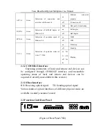
2.1.1 Front Panel LED Indicators   

There are 52 LED indicators with different functions at the front 

panel. Their functions are described as follows:   

Name 

Color 

Function 

Description 

PWR 

Green 

Indication of power supply status 

on 

Power supply is OK. 

off 

No power input. 

SYS 

Yellow 

Indication of operating 

on 

In normal operation. 

off 

Not in operation. 

SYL 

Red 

Indication  of  loss  of  frame  in 

optical link 

on 

Alarming of loss of frame 

in optical link. 

off 

In normal operation. 

LOS 

Red 

Indication  of  loss  of  signal  in 

optical link 

on 

Alarming of loss of signal 

in optical link. 

off 

In normal operation. 

E6 

Yellow 

Error signal in optical link≥10-6 

on 

Error  signal  in  optical 

link≥10

-6


off 

In normal operation. 

E3 

Red 

Error signal in optical link≥10-3 

on 

Error  signal  in  optical 

link≥10

-3


off 

In normal operation. 

E1L1-4 

Red 

Indication  of  E1  1-4  working 

status 

on 

Loss of signal in E1 1st 

off 

In normal operation. 

Summary of Contents for OP-4E1+ETH+32Vo

Page 1: ...8 3 6 ETHERNET INTERFACE 9 3 7 SERIAL INTERFACE RS232 RS485 RS422 DATA INTERFACE 9 3 8 FXO FXS TELEPHONE INTERFACE 9 CHAPTER 4 INSTALLATION 10 4 1 SAFETY REQUIREMENTS 10 4 2 INSPECTION UPON UNPACKING...

Page 2: ...contained herein the Company cannot be held liable for any harm or damage resulting from any omissions inaccuracies or errors contained in the manual Brief Introduction This User Manual describes the...

Page 3: ...me temporary construction sites which demand quick solutions to the need of telephone and data operation and the Village village Connection telephone accessing project which is now in progress 1 2 Fea...

Page 4: ...Voice Broadband Optical Multiplexer User Manual 4 1 9 inches structure with 1U height supported high single machine density and lower machine room occupancy...

Page 5: ...eir functions are described as follows Name Color Function Description PWR Green Indication of power supply status on Power supply is OK off No power input SYS Yellow Indication of operating on In nor...

Page 6: ...p off Stand by on for 1s and off for 4s Ringing 2 1 2 CONSOLE Interface Operating parameters of local and remote end devices can be configured through CONSOLE interface and meanwhile operating status...

Page 7: ...ype wires ridding the trouble of remaking the wires 2 2 3 VOICE Interface There are 8 RJ45 ports in a row that are the voice interface each of which can transfer 4 lines of telephone making 1 4 5 8 9...

Page 8: ...o ensure a stable operation Input Voltage AC 220V DC 48V Power Fluctuation 165VAC 265VAC or 36VDC 72VDC Power Consumption 50 W The power consumption will vary in result of the quantity difference of v...

Page 9: ...hone Interface Line Property Comply with the Technical specifications for telephone exchange equipment by Ministry of Posts and Telecommunications Voice encoding PCM encoding 64Kbps per line Relay Int...

Page 10: ...should be linked to the ground through earthed conductor To avoid electric shock the earthed conductor must be in connection with the ground Make sure that the product is correctly earthed before conn...

Page 11: ...wer cable please disconnect the power supply Connect the power supply again after operation And use the equipment under the operating condition required in the manual 4 4 Test The following tests shou...

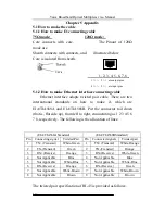
Page 12: ...that is flat side up from left to right enumerating as 1 2 3 4 5 6 7 8 respectively The following is the allocation of lines The twisted pair specification of RJ 45 is provided as follows EIA TIA568A...

Page 13: ...y use straight through cable the connect method of two ends are the same 2 Connect the equipment and switches or HUB cascadly use cross line cable the connect method of two ends are different Cross li...

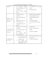
Page 14: ...WR is OFF 1 Control switch is not fully turned on 2 The power supply is not connected with correct polarity 3 Outside power source is not correctly plugged 4 Conductor is dropped into the frame causin...

Page 15: ...le properly 2 Change the network structure to reduce the multiple cascades of HUBER 3 Set proper operating mode 4 Set other device clock mode on the line E1 line alarms after the E1 interface is conne...

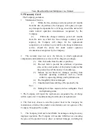
Page 16: ...m the date of purchase 4 The user fails to provide the certificate of purchase date or the serial number of the product indicates that the product has left the factory 36 months ago 5 Include but not...

Page 17: ...and Optical Multiplexer User Manual 17 not limited to loss of information resulting from defects of the product Product repair maintenance records Name OP 4E1 ETH 32Vo Device Num Repair Date Service N...

Reviews: