Voice Broadband Optical Multiplexer
User
Manual
12
Chapter 5 Appendix
5.1 How to make the cable
5.1.1 How to make E1 connecting cable
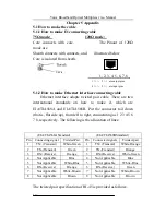
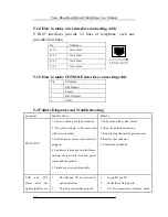
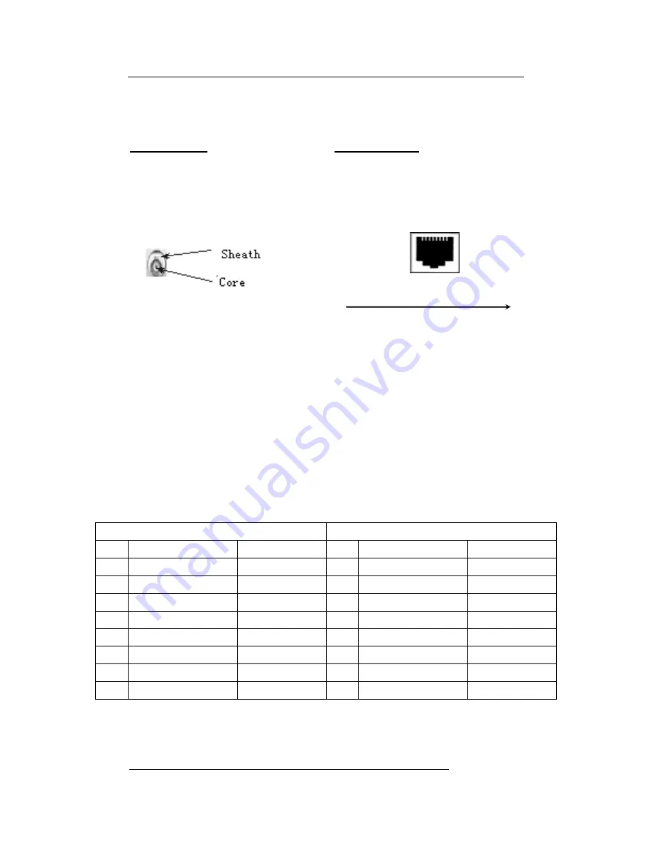
75Ω mode: 120Ω mode:
Core connects with core, The Pinout of 120Ω
mode are
Sheath connects with connects, and illustrated below
Core is isolated from sheath.
1, 2, 3, 4, 5, 6, 7, 8
5.1.2 How to make Ethernet interface connecting cable
Ethernet interface adopts twisted pair cable. There are two
international standards on how to make it, which are
EIA/TIA568A and EIA/TIA568B. Put the connector tail down
(that is, flat side up), from left to right, enumerating as 1 2 3 4 5 6
7 8, respectively. The following is the allocation of lines:
The twisted pair specification of RJ-45 is provided as follows:
(EIA/TIA568A Standard)
(EIA/TIA568BStandard)
Pin
Connecting signal
Twisted-Pair
Pin
Connected signals
Twisted-pair
1
TX+(Transmit)
White-Green
1
TX+(Transmit)
White-Orange
2
TX-(Transmit)
Green
2
TX-(Transmit)
Orange
3
RX+(Receive)
Orange
3
RX+(Receive)
White-Green
4
Not Applicable
Blue
4
Not Applicable
Blue
5
Not Applicable
White-Blue
5
Not Applicable
White-Blue
6
RX-(Receive)
Orange
6
RX-(Receive)
Green
7
Not Applicable
White-Brown
7
Not Applicable
White-Brown
8
Not Applicable
Brown
8
Not Applicable
Brown
1
(
+
)、
2
(
-
)
are output pins
4
(
+
)、
5
(
-
)
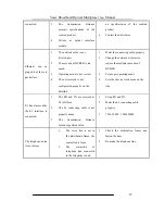
are input pins


