GRAFIK Eye
®
3000 Series Control Unit Installer’s Guide 11
R
Section 3:
Programming a GRAFIK Eye
®
Control Unit
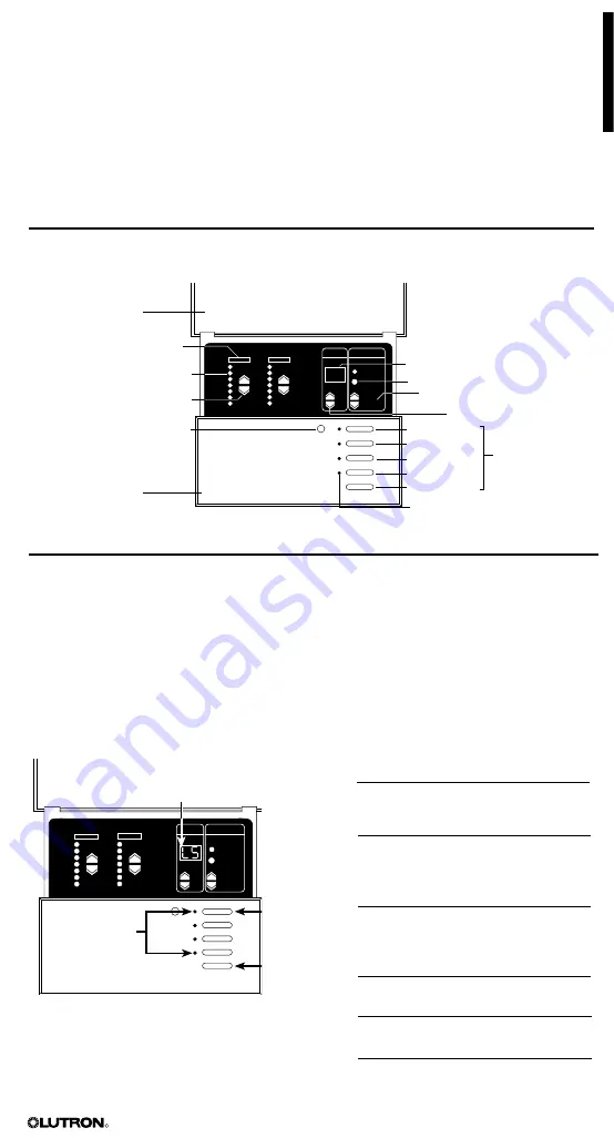
This section identifies buttons and indicators on a
GRAFIK Eye
3000 Series control unit . This
section also explains how to enter setup mode, program a control unit, adjust the high and low
end trim, and select a save mode . Most programming operations are typically performed only
once, when the control unit is installed . Other operations, such as selecting scenes and making
temporary adjustments, are performed as needed to achieve the right lighting and shade effects .
For systems with multiple control units, refer to page 20 for addressing .
NOTE: Lutron ships each control unit with factory-set programming. For a description of the
factory presets, refer to page 3
Control Unit Buttons and Indicators
The setup codes include:
FADE
TEMPORARY
MASTER
ZONES
ZONE 5
ZONE 6
M S
To enter (exit)
setup mode:
Press and
hold for
about three
seconds until
LEDs cycle
(stop cycling)
Scene LEDs
Use
5
and
6
to scroll through setup
codes (LS is the first code to display)
Entering and Exiting Setup Mode
You must enter setup mode to access the programming functions on the control unit .
To enter setup mode:
Press and hold the SCENE 1 and OFF buttons for about three sec-
onds, until the scene LEDs start cycling . When the buttons are released, the LEDs should
continue to cycle .
In setup mode, the FADE window displays the first setup code available for programming . To
scroll up and down through the menu of setup codes, press the FADE
5
or
6
buttons .
To exit setup mode:
Press and hold the SCENE 1 and OFF buttons for about three seconds,
until the scene LEDs stop cycling . The control unit returns to normal operating mode .
FADE
TEMPORARY
MASTER
ZONES
ZONE 1
ZONE 2
M S
00
Hinged cover
Zone label
Light level/shade position
LED bar graph
ZONE raise/lower buttons
Infrared wireless
remote control receiver
Faceplate
FADE window (if ‘S’ is lit, time is
in seconds, if ‘M’ is lit, time is in
minutes)
MASTER raise/lower buttons
FADE buttons
SCENE buttons
Scene 1
Scene 2
Scene 3
Scene 4
OFF
Scene indicator LEDs
TEMPORARY ZONES button
Code Stands for Description
Sd
Save modes Select from
several save
options (page 17) .
Sc
Scene
Set up any of the
scenes, including
unaffected zones
(page 16) .
A-
Address
Identify control
units for system
communications
(page 20) .
LS
Load Select Identify load types
(page 12) .
HE
High End
Set high end trim
(page 17) .
LE
Low End
Set low end trim
(page 17) .
Summary of Contents for 3000 Series
Page 20: ...2 ...
Page 99: ... R 032118b G3000 install chs 09 18 07 15 55 Page 3 ...
Page 100: ... R 032118b G3000 install chs 09 18 07 15 55 Page 4 ...
Page 106: ... R 4 3 2 1 4 3 2 1 3 2 1 4 032118b G3000 install chs 09 18 07 15 55 Page 10 ...
Page 109: ... R 032118b G3000 install chs 09 18 07 15 55 Page 13 ...
Page 116: ... R FADE TEMPORARY MASTER ZONES ZONE 5 ZONE 6 M S 2 3 1 4 ...
Page 117: ... R 032118b G3000 install chs 09 18 07 15 55 Page 21 ...
Page 118: ... R 5 032118b G3000 install chs 09 18 07 15 55 Page 22 ...
Page 119: ... 2011 R 032118b G3000 install chs 09 18 07 15 55 Page 23 ...


