


15
307–959
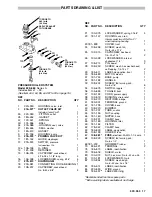
PARTS DRAWING
These parts numbers refer only to the parts illustrated on this page. See page 16 and 17 for the illustrations and
part numbers of other components in the system
REF
NO. PART NO. DESCRIPTION
QTY
REF
NO. PART NO. DESCRIPTION
QTY
60
218–954
VALVE, spray
SEE REPAIR KIT 218–960 BELOW
1
64 108–356
HOSE, fluid, nitrile rubber; cpld
3/8 npsm(m); 25’ (7.6 m)
2
85
108–228
NIPPLE, 3/8 npt
1
87
108–408
ADAPTER
1
88
220–237
WAND, tube
1
89
180–136
ADAPTER, tip
1
90
171–602
WASHER, tip
1
91
185–559
50
_
SPRAY TIP; 0.036” orifice
1
92
163–622
FINE FINISH TIP; 0.022” orifice
1
93
166–969
WASHER, tip
1
*Recommended tool box spare parts.
E
F
A
B
D
C
H
G
SPRAY VALVE REPAIR KIT 218–960
Includes items A through H
Individual parts not sold separately.
See page 14 for instructions.
87
TIGHTEN WITH
WRENCH
APPLY SEALANT
TO THREADS.
HOLD STEADY
WITH WRENCH.
60
64
85
64
88
89
93
91
90
92


