background image


3.8 

Connect Jet Cables to Robot Z Head 

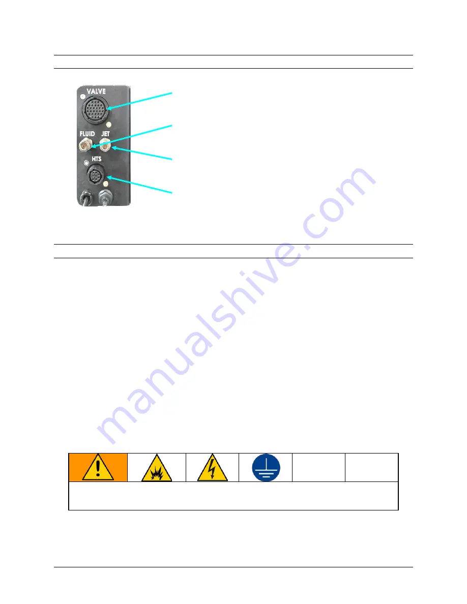
Note: Connect the cables in the order listed to avoid unintended dispensing (and the resultant mess). 


  Attach the Jet 

Valve

  Cable.  Align the connector and 

1.

twist the locking ring to tighten. 

  Attach the CLEAR 

Fluid

 Air Pressure tubing and push 

2.

it straight into the FLUID connector until it clicks. 

  Attach the BLACK 

Jet

 Air Pressure tubing and push it 

3.

straight into the JET connector until it clicks. 

  Attach the Height Sensor (

HTS

)  cable. Align the 

4.

connector and twist the locking ring to tighten. 


3.9 

Connect Components to Power  

There are four power connections for the UniXact Automated Jet Dispense System: 

  UniXact Tabletop Robot  

  Advanjet HV-2100C or HM-2600C Controller 

  Monitor 

  PC (via power adapter) 

 
A power cord/adapter set (P/N 25E557) with connectors for each of the regions listed is 
provided for the robot, the controller, and the monitor: 

  Standard 115 V, 10A cord for USA, Mexico, Canada, Taiwan, and similar 

  250V cord for continental Europe 

  Adapter for UK, Australia, and similar 

For the PC, a set of regional 320-C5 adapters is provided (P/N 25E758).  
 
The camera is powered through the robot via USB. The keyboard and mouse use 
batteries. 

The controller and robot  are grounded through their power cords.  Connect  the power 
cords to a properly grounded power source before operating.  


The equipment must be grounded to reduce the risk of static sparking and electric shock. Electric 
or  static sparking can cause fumes to ignite or explode. Improper grounding can cause electric 
shock. Grounding provides an escape wire for the electric current. 


Figure 12: 

Jet Connections on the 

Robot Z Head 

Page 12 of 18 

UniXact Automated Jet Dispense System Installation 

3A5913B 

Summary of Contents for UniXact B300

Page 1: ...l environments Not for use in explosive atmospheres or hazardous classified locations For professional use only Models B300 and B300 HM See page 3 for model information Important Safety Instructions R...

Page 2: ...Cables and Air Lines 10 3 6 Connect PC and Peripherals 11 3 7 Mount the Jet 11 3 8 Connect Jet Cables to Robot Z Head 12 3 9 Connect Components to Power 12 4 Power and Test Components 13 4 1 Turn On P...

Page 3: ...nsing Parameters Supplement 3A5914 UniXact Automated Jet Dispense System Software 3A6674 UniXact Automated Jet Dispense System Parts Models Model Part No Description B300 25B350 System B300 HV 2100 30...

Page 4: ...usage of the system can cause electric shock Turn off and disconnect power cord before servicing equipment Connect only to grounded electrical outlets Use only 3 wire extension cords Ensure ground pr...

Page 5: ...Sheets SDSs from distributor or retailer Check equipment daily Repair or replace worn or damaged parts immediately with genuine manufacturer s replacement parts only Do not alter or modify equipment...

Page 6: ...Camera Included Integrated Prime Purge Included Tip Detection Included Workpiece Detection Mechanical or Laser Data Storage PC Storage USB I O Signal Port 8 Inputs 8 Outputs Control Method PTP and CP...

Page 7: ...2 CAMERA 3 MECHANICAL HEIGHT SENSOR 4 PC 5 PRIME PURGE STATION 6 TACTILE SWITCH 7 LIGHTED START BUTTON 8 EMERGENCY STOP BUTTON 9 ADVANJET HV 2100C JET CONTROLLER 10 ADVANJET HM 2600C HOTMELT JET CONTR...

Page 8: ...e risk of static sparking and electric shock Electric or static sparking can cause fumes to ignite or explode Improper grounding can cause electric shock Grounding provides an escape wire for the elec...

Page 9: ...G BRACKET 1 SCREW SHBS M4 X 8 2 SCREWS SHBS M3 X 8 Y AXIS SHIPPING BRACKET 1 SCREW SHBS M4 X 8 2 SCREWS SHBS M3 X 8 Z AXIS LOCKING SCREW SPACER X AXIS REMOVE LOCKING BRACKET SCREWS REMOVE BRACKET APPL...

Page 10: ...luid Pressure Tubing CLEAR Robot Controller FLUID PRESSURE 3 Jet Pressure Tubing BLACK Robot Controller JET PRESSURE 4 Air In Tubing BLUE Robot Controller AIR IN 5 I O DB 26 Controller I O Robot I O P...

Page 11: ...st line 3 mm up as shown in Figure 9 center For 6 mmm nozzles align the jet mount bottom with the second line 6 mm up as shown in Figure 9 right Use a 3 mm wrench to tighten the four jet mount screws...

Page 12: ...er cord adapter set P N 25E557 with connectors for each of the regions listed is provided for the robot the controller and the monitor Standard 115 V 10A cord for USA Mexico Canada Taiwan and similar...

Page 13: ...on the Robot power wait for the beep before booting the PC and running the Dispense Pro Software This can take up to 40 seconds PC Use the power button on the PC front 5 4 2 Test Pneumatic Connections...

Page 14: ...he table In the navigation window of the DispensePro home screen click on a point in the 3 work surface area to move the robot The robot should move to that location Install the diaphragm and nozzle p...

Page 15: ...ome resistance to motion but each axis should move freely X Axis Move the Z head left and right Y Axis Move the work surface table back and forward Z Axis Move jet mount up and down Press the red Trig...

Page 16: ...ows Start icon then click the power button 2 and select Shut Down Monitor Use the main power button on the front of the monitor 3 Robot Use the Main power switch on the robot rear panel 4 Advanjet Con...

Page 17: ...Notes 3A5913B UniXact Automated Jet Dispense System Installation Page 17 of 18...

Page 18: ...ales injury to person or property or any other incidental or consequential loss shall be available Any action for breach of warranty must be brought within two 2 years of the date of sale GRACO MAKES...

Reviews: