background image

Technical Specifications 

54

334466F

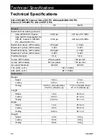
Technical Specifications

Ultra 395/

495

 PC 

Classic, 

Ultra 395 PC, Ultimate NOVA 395 PC, 

Classic S 395/495 PC, Ultra 395 PC Pro

US

Metric

Sprayer

Maximum fluid working pressure  

Ultra 395/495 PC Classic

3000 psi

207 bar, 20.7 MPa

Ultra 395 PC, Ultimate NOVA 
395 PC, Classic S 395/495 
PC, Ultra 395 PC Pro

3300 psi

228 bar, 22.8 MPa

Maximum Delivery (395 models)

0.54 gpm

2.0 lpm

Maximum Tip Size (395 models)

0.023

0.023

Maximum Delivery (495 models)

0.60 gpm

2.3 lpm

Maximum Tip Size (495 models)

0.025

0.025

Fluid Outlet npsm

1/4 in.

1/4 in.

Cycles (395 models)

700 per gallon

185 per liter

Cycles (495 models)

581 per gallon

154 per liter

Generator Minimum

3000 W

3000 W

110–120V, A, Hz

1Ø, 13, 50/60

220–240V, A, Hz

1Ø, 7, 50/60

Dimensions

Height

Stand

18.5 in.

47 cm

Lo-Boy

22.5 in. 

57.2 cm

Hi-Boy

28.25 in. (Handle down)

38.25 in. (Handle up)

71.8 cm (Handle down)

97.2 cm (Handle up)

Length

Stand

16 in.

40.6 cm

Lo-Boy

26.5 in.

67.3 cm

Hi-Boy

23.25 in.

59.1 cm

Width

Stand

14 in.

35.6 cm

Lo-Boy

20 in.

50.6 cm

Hi-Boy

20.5 in.

52.1 cm

Weight

Stand

43 lb.

20 kg

Lo-Boy

63 lb.

29 kg

Hi-Boy

66 lb.

30 kg

Summary of Contents for Ultimate NOVA 395 PC

Page 1: ... Maximum Working Pressure Ultra 395 PC Classic Ultra 495 PC Classic 3000 psi 207 bar 20 7 MPa Maximum Working Pressure See page 3 for additional model information Important Safety Instructions Read all warnings and instructions in this manual and related manuals Be familiar with the controls and the proper usage of the equipment Save these instructions Related Manuals Gun 311861 Contractor FTx 312...

Page 2: ...on 20 Spray 20 Clear Tip Clog 21 Digital Display 22 Cleanup 24 Maintenance 27 Troubleshooting 28 Mechanical Fluid Flow 28 Electrical 31 Stand Sprayers 40 Stand Sprayers Parts List 42 395 Lo Boy Sprayers 43 395 Lo Boy Sprayers Parts List 45 Hi Boy Sprayers 46 Hi Boy Sprayers Parts List 48 Accessories and Labels 49 Control Box 50 Control Box Parts List 51 Wiring Diagrams 52 110 120V 52 230V 53 Techn...

Page 3: ...Taiwan Ultra 395 PC 17C391 230 CEE 7 7 Classic S 395 PC 17C361 17C362 Classic S 495 PC 17E023 17E025 230 Europe Multi Classic S 495 PC 17E024 17E026 110 UK Classic S 395 PC 17C359 230 Asia ANZ Ultra 395 PC 17C390 17C408 230 ANZ Ultra 395 PC Pro 17C392 230 China Ultra 395 PC Classic 17C409 110474 Certified to CAN CSA C22 2 No 68 Conforms to UL 1450 ...

Page 4: ... repair or replacement of the cord or plug is required do not connect the grounding wire to either flat blade terminal The wire with insulation having an outer surface that is green with or without yellow stripes is the grounding wire Check with a qualified electrician or serviceman when the grounding instructions are not completely understood or when in doubt as to whether the product is properly...

Page 5: ... unless they are antistatic or conductive Connect to a grounded outlet and use grounded extensions cords Do not use a 3 to 2 adapter Do not use a paint or a solvent containing halogenated hydrocarbons Do not spray flammable or combustible liquids in a confined area Keep spray area well ventilated Keep a good supply of fresh air moving through the area Sprayer generates sparks Keep pump assembly in...

Page 6: ...e of producing 3300 psi Use Graco replacement parts or accessories that are rated a minimum of 3300 psi Always engage the trigger lock when not spraying Verify the trigger lock is functioning properly Verify that all connections are secure before operating the unit Know how to stop the unit and bleed pressure quickly Be thoroughly familiar with the controls EQUIPMENT MISUSE HAZARD Misuse can cause...

Page 7: ...utate fingers and other body parts Keep clear of moving parts Do not operate equipment with protective guards or covers removed Pressurized equipment can start without warning Before checking moving or servicing equipment follow the Pressure Relief Procedure and disconnect all power sources TOXIC FLUID OR FUMES HAZARD Toxic fluids or fumes can cause serious injury or death if splashed in the eyes ...

Page 8: ...61a J A G F L H F A ON OFF Switch B Pressure Control D Prime Valve F Tip Guard G Spray Tip H Gun J Airless Hose K Power Cord L Trigger Lock M Drain Tube N Fluid Intake P Pump R Fluid Outlet S Power Cord Wrap U Filter V Finger Guard TSL Fill Point Model Serial Tag Not shown located on bottom of unit ...

Page 9: ...J A G F L H F A ON OFF Switch B Pressure Control D Prime Valve F Tip Guard G Spray Tip H Gun J Airless Hose K Power Cord L Trigger Lock M Drain Tube N Fluid Intake P Pump R Fluid Outlet U Filter V Finger Guard TSL Fill Point Model Serial Tag Not shown located on bottom of unit ...

Page 10: ...Component Identification 10 334466F Hi Boy Models D T K S M N U V P R B ti24837a J A G F L H F ...

Page 11: ...B Pressure Control D Prime Valve F Tip Guard G Spray Tip H Gun J Airless Hose K Power Cord L Trigger Lock M Drain Tube N Fluid Intake P Pump R Fluid Outlet S Hanger T Filter U Finger Guard TSL Fill Point V Pail Hook Model Serial Tag Not shown located on bottom of unit ...

Page 12: ...reduce sprayer performance Pails Solvent and oil based fluids follow local code Use only conductive metal pails placed on a grounded surface such as concrete Do not place pail on a non conductive surface such as paper or cardboard which interrupts grounding continuity Always ground a metal pail connect a ground wire to the pail Clamp one end to the pail and the other end to a true earth ground suc...

Page 13: ... trigger lock 4 Hold a metal part of the gun firmly to a grounded metal pail Trigger the gun to relieve pressure 5 Engage the trigger lock This equipment stays pressurized until pressure is manually relieved To help prevent serious injury from pressurized fluid such as skin injection splashed fluid and moving parts follow the Pressure Relief Procedure whenever sprayer is stopped and before sprayer...

Page 14: ...ose is clogged or that pressure has not been fully relieved a VERY SLOWLY loosen the tip guard retaining nut or the hose end coupling to relieve pressure gradually b Loosen the nut or coupling completely c Clear hose or tip obstruction Trigger Lock Always engage the trigger lock when sprayer is stopped to prevent the gun from being triggered accidentally by hand or if dropped or bumped ti24607a ti...

Page 15: ...e perform setup procedure When first setup is performed remove shipping plug from fluid outlet 1 Connect Graco airless hose to fluid outlet Use wrenches to tighten securely 2 Connect other end of hose to gun 3 Use wrenches to tighten securely 4 Engage trigger lock ti24616a ti24633a ti24931a ...

Page 16: ... premature packing wear Do this daily or each time you spray a Place the TSL bottle nozzle into the top center opening in the finger guard at the front of the sprayer b Squeeze bottle to dispense enough TSL to fill the space between the pump rod and packing nut seal 8 Make certain ON OFF switch is OFF 9 Plug power supply cord into a properly grounded electrical outlet 10 Turn prime valve down ti24...

Page 17: ...ntake with drain tube in grounded metal pail partially filled with flushing fluid Use water to flush water based paint or mineral spirits to flush oil based paint 20 Turn ON OFF switch to ON position 21 Turn prime valve horizontal Disengage trigger lock 22 Hold a metal part of the gun firmly to a grounded metal pail Trigger gun and flush for one minute 23 Turn ON OFF switch to OFF position 24 Enga...

Page 18: ...Place fluid intake in paint pail Place drain tube in waste pail 5 Increase pressure 1 2 turn to start motor Allow paint to circulate through sprayer until paint flows out the drain tube 6 Turn prime valve horizontal Disengage trigger lock 7 Hold gun against grounded metal waste pail Trigger gun until paint appears ti24603b ti24644a ti24645b s ti24646a ...

Page 19: ...ure page 13 then tighten all fittings and repeat Startup procedure If there are no leaks continue with the next step 10 Screw tip assembly onto gun and tighten See Spray Tip Installation page 20 For gun assembly instructions see separate gun manual ti24647a 1 m ti24649a 20 s High pressure spray is able to inject toxins into the body and cause serious bodily injury Do not stop leaks with hand or ra...

Page 20: ...Tip 3 Screw assembly onto gun Tighten Spray When a RAC X FF LP Fine Finish Low Pressure reversible spray tip is used spraying pressure can be lowered Spraying at a lower pressure results in less overspray and reduces spray tip wear Adjust the sprayer pressure to minimize overspray ti24653a C B A ti24664a Atomized evenly distributed fan pattern Tails ti24652a ti31221a ...

Page 21: ...back and forth overlap by 50 4 Trigger gun after moving Release trigger before stopping For additional spraying information see separate gun manual Clear Tip Clog 1 Release trigger Engage trigger lock Rotate Spray Tip Disengage trigger lock Trigger gun at waste area to clear clog 2 Engage trigger lock Return Spray Tip to original position Disengage trigger lock and continue spraying ti24669a ti246...

Page 22: ...rounded outlet Turn ON OFF switch to ON position 3 The pressure is displayed Dashes indicate pressure is less than 200 psi 14 bar 1 4 MPa 4 Press and hold display button to change pressure units psi bar or MPa Stored Data Display 1 Turn ON OFF switch to OFF position 2 To enter Stored Data Mode press and hold display button and turn ON OFF switch to ON position ti24651a ti24644a ti2786a ti2888a ti2...

Page 23: ... time in hours is displayed 5 Press display button again to display Data Point 3 This will be the last error code 6 To erase last error code press and hold display button 7 Press display button again to display Data Point 4 The software revision is displayed 8 Press display button again to return to Data Point 1 9 Turn ON OFF switch to OFF position to exit Stored Data ti2824a ti24586a ...

Page 24: ...y Tip For additional information see separate gun manual 3 Remove fluid intake and drain tube from paint wipe excess paint off outside 4 Place fluid intake in flushing fluid Use water for water base paint and mineral spirits for oil based paint Place drain tube in waste pail ti24592a ti24709a ti24710a ...

Page 25: ...til the pump runs steady and flushing fluid appears 7 Stop triggering gun Move gun to waste pail hold gun against pail trigger gun to thoroughly flush system 8 While continuing to trigger gun turn prime valve down Then release gun trigger Allow flushing fluid to circulate until fluid comes out of drain tube clear 9 Raise fluid intake above flushing fluid ti24712a ti24713a ti24714a ...

Page 26: ...h to OFF position Disconnect power to sprayer 13 Remove filter from gun and sprayer if installed Clean and inspect Install filter See separate gun manual 14 If flushing with water flush again with mineral spirits or Pump Armor to leave a protective coating to prevent freezing or corrosion 15 Wipe sprayer hose and gun with a rag soaked in water or mineral spirits ti24649a 20 s ti24717a ti24718a ti2...

Page 27: ...t be 1 2 in 13mm minimum length NOTE Brushes do not wear at the same rate on both sides of motor Check both brushes Every 1000 gallons 3785 liters Check sprayer stall With sprayer gun NOT triggered sprayer motor should stall and not restart until gun is triggered again If sprayer starts again with gun NOT triggered inspect pump for internal external leaks and check prime valve for leaks Every 1000...

Page 28: ...ual Spray tip clogged Relieve pressure Check and clean spray tip Paint supply Refill and reprime pump Intake strainer clogged Remove and clean then reinstall Intake valve ball and piston ball are not seating properly Remove intake valve and clean Check balls and seats for nicks replace if necessary See pump manual Strain paint before using to remove particles that could clog pump Fluid filter or t...

Page 29: ...ce brushes Broken and misaligned motor brush springs Rolled portion of spring must rest squarely on top of brush Replace spring if broken Realign spring with brush Motor brushes are binding in brush holders Clean brush holders remove carbon dust with a small cleaning brush Align brush lead with slot in brush holder to assure free vertical brush movement Motor runs but pump does not stroke Connecti...

Page 30: ...sible during priming Intake valve is leaking Clean intake valve Be sure ball seat is not nicked or worn and that ball seats well Reassemble valve Pump packings are worn Replace pump packings See pump manual Paint is too thick Thin the paint according to supplier recommendations Sprayer operates for 5 to 10 minutes then stops Pump packing nut too tight When pump packing nut is too tight the packing...

Page 31: ...ontrol board status light Turn the ON OFF switch OFF remove the control coverthenturnpowerbackON Observe the status light Blinking LED total count equals the error code for example two blinks equals CODE 02 Keep clear of electrical and moving parts during troubleshooting procedures To avoid electrical shock hazards when covers are removed for troubleshooting wait 7 seconds after disconnecting powe...

Page 32: ...nd go to next step Install new transducer Connect power turn ON OFF switch ON and control knob 1 2 turn clockwise Replace control board if sprayer does not run properly Sprayer does not run at all AND Display shows E 03 OR Control board status light blinks 3 times repeatedly Check transducer or transducer connections control board is not detecting a pressure signal Turn ON OFF switch OFF and disco...

Page 33: ... sprayer If motor runs check for locked or frozen pump or drive train If sprayer does not run continue to step 2 2 Turn ON OFF switch OFF and disconnect power to sprayer 3 Disconnect motor connector s from control board socket s Check that motor connector and control board contacts are clean and secure If contacts are clean and secure continue to step 4 4 Connect a DC voltmeter across the two moto...

Page 34: ...n open is found replace the motor 7 Check motor thermal protection Motor should be at ambient temperature for this test Connect the yellow leads from the motor to an Ohm meter Meter should indicate continuity or Ohms depending on the motor type Problem What to Check How to check YELLOW BLACK RED ti24723a 1 3 ohms YELLOW BLACK RED ti24725a ...

Page 35: ... light blinks 6 times repeatedly Motor is hot or there is a fault in the motor thermal device Allow sprayer to cool If sprayer runs when cool correct cause of overheating Keep sprayer in cooler location with good ventilation Make sure motor air intake is not blocked If sprayer still does not run replace motor Sprayer does not run at all AND Display shows E 08 OR Control board status light blinks 8...

Page 36: ...es do not wear at the same rate on both sides of motor Check both brushes Replace brushes Broken or misaligned motor brush springs Rolled portion of spring must rest squarely on top of brush Replace spring if broken Realign spring with brush Motor brushes may be binding in brush holders Clean brush holders Remove carbon with small cleaning brush Align brush leads with slot in brush holder to assur...

Page 37: ...troubleshooting Sprayer Will Not Run see following pages for steps See Step 2 Do you have over 100 VAC 220 VAC for 230v units Repair or replace power cord See Step 3 Is there Continuity through the thermal switch wires See Step 4 Does the motor run Replace the potentiometer Replace the transducer Replace the control board If motor is hot let cool and retest If Step 3 still shows no continuity repl...

Page 38: ...Black J11 J8 J7 N L C15 White Control Board Step 2 Plug power cord in and turn switch ON Connect Probes to ON OFF switch Turn meter to AC Volts ti24728a BEEP Yellow Thermistor Wires to motor Step 3 Check motor thermal switch Unplug yellow wires Meter should read continuity NOTE Motor should be cool during reading ti24729a J8 Control Board Step 4 Disconnect potentiometer Plug power cord in and turn...

Page 39: ...g Plumb pressure gauge into paint hose plug sprayer in and turn power switch ON Does sprayer reach or exceed its maximum pressure Mechanical problem See the proper fluid pump manual for the sprayer for further troubleshooting procedures Is the control board status light on NO Replace the control board NO Replace the control board NO YES YES Unplug the transducer from control board Does motor stop ...

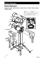
Page 40: ...d Sprayers Models 17C314 17C359 17C361 17C390 17C391 17C392 17C409 17E023 17E024 826196 59 67 54 54b 54a 47 47 23 65 12 12 71 68 63 53 ti24754a 61 46 1 2 Ref Torque 140 160 in lb 15 8 18 1 N m 30 35 in lb 3 4 4 0 N m 1 2 See page 50 ...

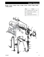
Page 41: ...C390 17C391 17C392 17C409 17E023 17E024 826196 42 69 66 22 12 70 43 132 45 91 60 60 57 55 39 62 76 91 47 ti24753a 52 41 40 44 26 28 29 27 25 Ref Torque 140 160 in lb 15 8 18 1 N m 30 35 in lb 3 4 4 0 N m Hammer tight 25 30 ft lb 33 9 40 7 N m 1 2 3 4 1 2 3 4 ...

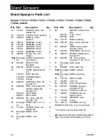
Page 42: ...ncludes 132 1 46 See page 49 HOSE cpld 1 4 in x 50 ft 1 47 117493 SCREW mach hex washer hd 9 52 See page 49 LABEL front 1 53 See page 49 LABEL side 1 54 MOTOR includes54a 54b 1 287015 110V 120V 287060 230V 54a 118716 RING retaining 1 54b 248189 FAN motor includes 54a 1 55 246381 HOSE drain stand includes 39 62 1 57 246385 STRAINER 7 8 14 unf 1 59 15E823 FRAME standmount includes 67 1 60 246386 KIT...

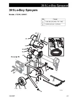
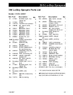
Page 43: ...ayers 334466F 43 395 Lo Boy Sprayers Models 17C315 826197 59 54 47 23 12 75 133 134 135 69 150 68 71 53 54a 54b 65 63 ti24829a 61 46 Ref Torque 140 160 in lb 15 8 18 1 N m 30 35 in lb 3 4 4 0 N m 1 2 1 2 See page 50 ...

Page 44: ...466F Models 17C315 826197 45 47 42 47 43 41 132 22 52 12 70 91 60 60 14 57 55 62 ti24826a 39 117 40 44 26 28 29 27 25 1 2 3 4 Ref Torque 140 160 in lb 15 8 18 30 35 in lb 3 4 4 0 N m Hammer tight 25 30 ft lb 33 9 40 7 N 1 2 3 4 ...

Page 45: ...x washer hd 8 52 See page 49 LABEL front 1 53 See page 49 LABEL side 1 54 287015 MOTOR includes54a 54b 1 54a 118716 RING retaining 1 54b 248189 FAN motor includes 54a 1 55 246381 HOSE drain stand includes 39 62 1 57 246385 STRAINER 7 8 14 unf 1 59 246250 FRAME cart lo 1 60 246386 KIT hose suction includes 14 57 62 91 1 61 See page 49 GUN spray not shown 1 62 276888 CLIP drain line 1 63 See page 49...

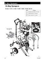
Page 46: ...odels 17C317 17C362 17C408 17E025 17E026 826198 59 54 54a 54b 47 75 23 12 95 53 133 134 135 69 67 179 178 178 177 65 63 ti24834b 61 60 1 2 3 See page 50 Ref Torque 140 160 in lb 15 8 18 1 N m 30 35 in lb 3 4 4 0 N m 23 27 in lb 2 6 3 1 N m 1 2 3 ...

Page 47: ...2 17C408 17E025 17E026 826198 40 44 42 26 28 29 27 47 43 41 132 45 22 52 12 70 91 55 39 136 137 60 57 14 84 96 62 ti24830a 25 117 Ref Torque 140 160 in lb 15 8 18 1 N m 30 35 in lb 3 4 4 0 N m Hammer tight 25 30 ft lb 33 8 40 6 N m 1 2 3 4 4 3 1 2 ...

Page 48: ...ee page 49 LABEL side 1 54 MOTOR includes 54a 54b 1 287015 110V 120V 287060 230V 54a 118716 RING retaining 1 54b 248189 FAN motor includes 54a 1 55 287952 HOSE drain includes 39 1 57 246385 STRAINER 7 8 14 unf 1 59 17C485 FRAME cart hi 1 60 17C992 KIT stinger tube includes 14 57 84 91 96 61 See page 49 GUN spray 1 62 276888 CLIP drain line 1 63 See page 49 LABEL danger 1 65 See page 49 LABEL warni...

Page 49: ...C408 17A134 240794 17C823 17C824 288427 288436 15H087 195792 17C391 17A134 240794 17C823 17C824 288427 288436 15H086 195792 17C392 17A134 240794 17C963 17C962 17C926 15H087 195792 17C409 17A134 247340 17C856 17C859 16X214 15H087 195792 17E023 17E024 17E025 17E026 222385 240794 17E046 17E047 288438 16G596 826196 826197 826198 222385 826079 17C825 17C826 826085 15B516 195793 288526 Kit accessory hop...

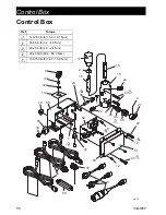
Page 50: ... 4 24 36 38 27 17 18 2 3 37 11 19 58 30 6 7 50 12 12 51 49 16 35 26 5 133 56 90 24 134 ti24755b 91 Ref Torque 140 160 in lb 15 8 18 1 N m 30 35 in lb 3 4 4 0 N m 20 25 in lb 2 3 2 8 N m 37 43 ft lb 50 2 58 3 N m 130 150 in lb 14 7 16 9 N m 1 2 5 6 7 1 5 2 7 5 6 1 ...

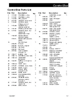
Page 51: ... BASE valve 1 37 17D888 POTENTIOMETER assembly 1 38 243222 TRANSDUCER pressure control includes 3 1 47 117493 SCREW mach hex washer hd 4 48 276868 BOX control 1 49 CONTROL board 1 246378 110V UK 246379 120V US Japan 246380 230V Europe Asia ANZ 24X292 230V China 24X752 230V 495 models 3000 psi 207 bar 24X751 230V 495 models 3300 psi 228 bar 50 276882 COVER control 1 287098 DIGITAL display includes ...

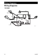
Page 52: ...Wiring Diagrams 52 334466F Wiring Diagrams 110 120V ON OFF Switch Power Plug from Motor Red White Black Green 2 x White Black Black Black ti2471a ...

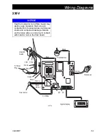
Page 53: ... Exposed wires could cause shorts and component damage Bundle and tie loose wires so none lay in contact with inductor coil on the filter board ti2478x L1 L2 Digital Display Potentiometer Filter Board Inductor Coil Brown Brown Black Black ON OFF Switch To Power Plug From Motor Green 2 x White Black white Blue Blue Red Transducer TP1 TP2 ...

Page 54: ...ximum Delivery 495 models 0 60 gpm 2 3 lpm Maximum Tip Size 495 models 0 025 0 025 Fluid Outlet npsm 1 4 in 1 4 in Cycles 395 models 700 per gallon 185 per liter Cycles 495 models 581 per gallon 154 per liter Generator Minimum 3000 W 3000 W 110 120V A Hz 1Ø 13 50 60 220 240V A Hz 1Ø 7 50 60 Dimensions Height Stand 18 5 in 47 cm Lo Boy 22 5 in 57 2 cm Hi Boy 28 25 in Handle down 38 25 in Handle up ...

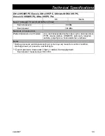
Page 55: ... steel PTFE Acetal leather UHMWPE aluminum tungsten carbide polyethylene fluoroelastomer urethane Notes Startup pressures and displacement per cycle may vary based on suction condition discharge head air pressure and fluid type Sound pressure measured 3 feet 1 meter from equipment Sound power measured per ISO 3744 Ultra 395 495 PC Classic Ultra 395 PC Ultimate NOVA 395 PC Classic S 395 495 PC Ultr...

Page 56: ...s of parts labor and transportation THIS WARRANTY IS EXCLUSIVE AND IS IN LIEU OF ANY OTHER WARRANTIES EXPRESS OR IMPLIED INCLUDING BUT NOT LIMITED TO WARRANTY OF MERCHANTABILITY OR WARRANTY OF FITNESS FOR A PARTICULAR PURPOSE Graco s sole obligation and buyer s sole remedy for any breach of warranty shall be as set forth above The buyer agrees that no other remedy including but not limited to inci...

Page 57: ...apolis International Offices Belgium China Japan Korea GRACO INC AND SUBSIDIARIES P O BOX 1441 MINNEAPOLIS MN 55440 1441 USA Copyright 2014 Graco Inc All Graco manufacturing locations are registered to ISO 9001 www graco com Revision F May 2017 Graco Information For the latest information about Graco products visit www graco com For patent information see www graco com patents TO PLACE AN ORDER co...

Reviews: