background image

Repair

26

312066ZAD

Repair

Before Beginning Repair

1.

Flush if necessary; see Flushing.

2.

Park component A pump.

a.

Press

.

b.

Trigger gun until pump A stops. After fluid pres-

sure drops below 700 psi (7.9 MPa, 79 bar),

motor will run until component A pump is at bot-

tom of its stroke, then shut off.

c.

Check ISO reservoir for component A pump. Fill

wet cup on component B pump. Refer to Reac-

tor Operation manual 312065.

3. Turn main power OFF

.

4.

Relieve pressure.

Pressure Relief Procedure

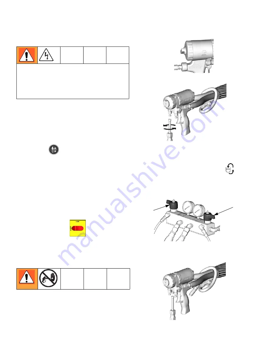
1.

Relieve pressure in gun and perform gun shutdown
procedure. See gun manual.

2.

Engage gun piston safety lock.

3.

Close gun fluid manifold valves A and B.

4.

Shut off feed pumps and agitator, if used.

5. Turn PRESSURE RELIEF/SPRAY valves (SA, SB)

to PRESSURE RELIEF/CIRCULATION

. Route

fluid to waste containers or supply tanks. Ensure
gauges drop to 0.

6.

Disconnect gun air line and remove gun fluid mani-
fold.

Repairing this equipment requires access to parts
that may cause electric shock or other serious injury if
work is not performed properly. Have a qualified elec-
trician connect power and ground to main power
switch terminals, see operation manual. Be sure to
shut off all power to the equipment before repairing.

ti2409a

ti2421a

SA

SB

ti2554a

Summary of Contents for SERIES F

Page 1: ...r professional use only Not approved for use in European explosive atmosphere locations See pages 3 and 4 for model information including maximum working pressure and approvals Important Safety Instructions Read all warnings and instructions in this manual Save these instructions 312066ZAD EN WL E Model E XP1 Shown ...

Page 2: ...otor Control Failure E 30 and E XP2 only 18 E32 Motor Control Overtemperature 19 Communication Diagnostic Codes 19 E30 Momentary loss of communication 19 E99 Loss of communication 19 Troubleshooting 20 Reactor Electronics 21 Primary Heaters A and B 23 Hose Heat System 24 Repair 26 Before Beginning Repair 26 Pressure Relief Procedure 26 Flushing 27 Pump Removal 27 Pump Installation 29 Drive Housing...

Page 3: ...tput per Cycle A B gal liter Maximum Fluid Working Pressure psi MPa bar 259026 F 78 230V 1 17 900 10 200 30 13 5 0 0272 0 1034 2000 14 140 259031 F 34 400V 3 17 900 10 200 30 13 5 0 0272 0 1034 2000 14 140 259035 F 50 230V 3 17 900 10 200 30 13 5 0 0272 0 1034 2000 14 140 259057 F 100 230V 1 23 000 15 300 30 13 5 0 0272 0 1034 2000 14 140 259058 F 62 230V 3 23 000 15 300 30 13 5 0 0272 0 1034 2000...

Page 4: ...ual English Reactor Electrical Diagrams Part Description 312067 Reactor Electric Proportioner Electrical Diagrams English Displacement Pump Part Description 309577 Electric Reactor Displacement Pump Repair Parts Manual English Reactor Data Reporting Kit Part Description 309867 Instruction Parts Manual English Fusion Spray Gun Part Description 309550 Instruction Parts Manual English Heated Hose Par...

Page 5: ...proved containers and dispose of it according to applicable guidelines PERSONAL PROTECTIVE EQUIPMENT Always wear appropriate personal protective equipment and cover all skin when spraying servicing equipment or when in the work area Protective equipment helps prevent serious injury including long term exposure inhalation of toxic fumes mists or vapors allergic reaction burns eye injury and hearing...

Page 6: ...RTS HAZARD Do not use 1 1 1 trichloroethane methylene chloride other halogenated hydrocarbon solvents or flu ids containing such solvents in pressurized aluminum equipment Such use can cause serious chem ical reaction and equipment rupture and result in death serious injury and property damage EQUIPMENT MISUSE HAZARD Misuse can cause death or serious injury This equipment is for professional use o...

Page 7: ...removed Pressurized equipment can start without warning Before checking moving or servicing equipment follow the Pressure Relief Procedure in this manual Disconnect power or air supply BURN HAZARD Equipment surfaces and fluid that s heated can become very hot during operation To avoid severe burns do not touch hot fluid or equipment Wait until equipment fluid has cooled completely WARNING ...

Page 8: ...r a properly fitting respirator which may include a sup plied air respirator Ventilate the work area according to instructions in the fluid manufacturer s SDS Avoid all skin contact with isocyanates Everyone in the work area must wear chemically impermeable gloves protective clothing and foot coverings as recommended by the fluid manufacturer and local regula tory authority Follow all fluid manufa...

Page 9: ...e respiratory protection Always wear a properly fitting respirator which may include a sup plied air respirator Ventilate the work area according to instructions in the fluid manufacturer s SDS Avoid all skin contact with isocyanates Everyone in the work area must wear chemically impermeable gloves protective clothing and foot coverings as recom mended by the fluid manufacturer and local regulator...

Page 10: ...l types used in your equipment requires special attention to avoid equipment damage and downtime When changing materials flush the equipment multiple times to ensure it is thoroughly clean Always clean the fluid inlet strainers after flushing Check with your material manufacturer for chemi cal compatibility When changing between epoxies and urethanes or polyureas disassemble and clean all fluid co...

Page 11: ... models only Jumper wire on J1 connector between module 3 and dis play 4 is loose or incorrectly wired Checks Check which zone is displaying the E01 error 1 Check that connector B is firmly plugged into tem perature control board see FIG 5 page 40 2 Clean and re plug connections 3 Check connections between the temperature control board and overtemperature switches A and B 308 and between temperatu...

Page 12: ...the power module is not the cause 8 Verify continuity of heater elements with an ohmme ter see page 42 E02 High zone current 1 Turn main power OFF 2 Relieve pressure page 26 3 Disconnect hose connector D at Reactor 4 Using an ohmmeter check between the two termi nals of the connector D There should be no conti nuity 5 Exchange zone module with another one Turn zone on and check for error If error ...

Page 13: ...for the hose zone test FTS by plugging directly into machine 5 To verify heater control module is not causing the problem use a wire to short circuit the two pins cor responding to the FTS red and yellow for A or B zone red and purple for hose The display will show the control heater module temperature 6 If an error occurred for the hose zone temporarily use the current control mode Refer to React...

Page 14: ...ed amount of time varies for different warnings or until main power is turned OFF then ON Alarms can also be cleared except for code 23 by pressing Code Code Name Alarm A or Warning W Corrective Action page 21 No transducer compo nent A A 16 22 No transducer compo nent B A 16 23 High fluid pressure A 16 24 Pressure imbalance A W to select see page 37 16 25 High line voltage A 18 26 Low line voltag...

Page 15: ...tor pressure trans ducer to use as a test transducer The test is done without removing the existing pressure transducers from the fluid manifold a Unplug the A transducer from the Motor con trol board socket page 39 and replace with test transducer b Turn on the Reactor master power If the error is gone turn off the Reactor main power remove test transducer and replace A transducer If the error pe...

Page 16: ...Continue dropping the original high side pressure the digi tal display should stop dropping Repeat the pro cess to check the other pressure transducer The last test determines if the pressure transducer has failed or if the socket on the pressure control board has gone bad 1 Swap the transducer plug ins on the motor control board J3 and J8 for the E 20 and E XP1 J3 and J5 for the E30 and E XP1 2 R...

Page 17: ...umpered properly If jumpered properly then it would appear that the problem is with in the motor control board E28 High current in motor Check motor control board 1 Turn the master power off 2 Disconnect socket J4 E 20 E XP1 J1 E 30 E XP2 on the motor control board 3 Turn the master power back on 4 If the E28 error did not go away then there is a prob lem with the motor control board Replace board...

Page 18: ...otor failure capacitor failure shorted or frayed wiring or inadequate power supply Perform the follow ing procedure before replacing the motor control board 1 Turn main power OFF Disconnect power supply 2 Relieve pressure page 26 3 Perform the following inspections a Motor failure Inspect the motor commutator by removing the top brush see Brush Removal page 33 Rotate the motor inspecting the whole...

Page 19: ...mes If communications are recon nected the display can show the E30 for a short time no more than about two seconds It should not be pos sible for E30 to be shown continuously unless there is a loose connection causing the display and the board to continuously lose and regain communication Check all wiring between the display and the corre sponding control board E99 Loss of communication Communica...

Page 20: ... for free movement Shorted armature Replace motor page 36 Check motor commutator for burn spots or other damage Remove motor Have motor shop resurface commutator if possible Damaged motor control board Replace board See page 37 Fan not working Blown fuse Replace page 39 Loose wire Check Defective fan Replace page 39 Pump output low Obstructed fluid hose or gun fluid hose ID too small Open clear us...

Page 21: ...board with connection to heater control board If temperature display illuminates heater control board is causing problem Otherwise display cable or display is failing Pressure display does not illuminate Display disconnected Check cable connections page 49 Display cable damaged or corroded Clean connections replace cable if is damaged Defective circuit board Swap display connection to motor contro...

Page 22: ...cable if is damaged Ribbon cable on display circuit board disconnected or broken Connect cable page 49 or replace Broken display button Replace page 49 Red stop button does not work Broken button fused contact Replace page 49 Loose wire Check connections page 49 Fan not working Blown fuse Verify with ohmmeter replace if nec essary page 49 Loose wire Check fan wire Defective fan Replace page 49 PRO...

Page 23: ...of primary heat is abnormal high temperature overshoots or E01 error occurs intermittently Dirty thermocouple connections Examine connection of thermocou ples to long green plug on heater control board Unplug and re plug thermocouple wires cleaning off any debris Unplug and re plug long green connector Thermocouple not contacting heater element Loosen ferrule nut N push in ther mocouple 310 so tip...

Page 24: ...rature not to increase it Ambient temperature is too cold Increase A and B setpoints to increase fluid temperature and keep it steady Flow too high Use smaller mix chamber Decrease pres sure Hose was not fully preheated Wait for hose to heat to correct tempera ture before spraying Low supply voltage Verify line voltage Low line voltage signifi cantly reduces power available to hose heat system aff...

Page 25: ...lement With hose heat on and temperature set point above displayed hose zone tem perature verify voltage between connectors at each section of hose Voltage should drop incrementally for each section of hose further from Reactor Use safety precautions when hose heat is turned on No hose heat Loose hose electrical connections Check connections Repair as necessary Circuit breakers tripped Reset break...

Page 26: ...perform gun shutdown procedure See gun manual 2 Engage gun piston safety lock 3 Close gun fluid manifold valves A and B 4 Shut off feed pumps and agitator if used 5 Turn PRESSURE RELIEF SPRAY valves SA SB to PRESSURE RELIEF CIRCULATION Route fluid to waste containers or supply tanks Ensure gauges drop to 0 6 Disconnect gun air line and remove gun fluid mani fold Repairing this equipment requires a...

Page 27: ...h a mois ture free plasticizer or oil Do not use water Pump Removal 1 Shut off and heat zones 2 Flush pump 3 If pumps are not parked press Trigger gun until pumps stop 4 Turn main power off Disconnect power supply 5 Shut off both feed pumps Close both fluid inlet ball valves B 6 Turn both PRESSURE RELIEF SPRAY valves SA SB to PRESSURE RELIEF Route fluid to waste containers or supply tanks Ensure g...

Page 28: ...xpose rod retaining pin Push retaining wire clip up Push pin out Continue unscrewing pump 10 Disconnect fluid inlet C and outlet D Also discon nect steel outlet tube from heater inlet 11 Push retaining wire clip E up Push pin F out Loosen locknut G by hitting firmly with a non sparking hammer Unscrew pump Use drop cloth or rags to protect Reactor and sur rounding areas from spills Steps 7 9 apply ...

Page 29: ...il fluid out let D is aligned with steel tube and top threads are 1 16 in 2 mm of bearing face N 3 Tighten locknut G by hitting firmly with a non sparking hammer 4 Reconnect fluid inlet C and outlet D 5 Go to step 13 Steps 1 5 supply to pump B To reconnect pump A proceed to step 6 C D F E G M N 1 TI3765a 1 Flat side faces up 1 Lubricate threads with ISO oil or grease 2 2 2 2 3 Pump top threads mus...

Page 30: ... 9 Connect component A outlet tube loosely at pump and at heater Line up tube then tighten fittings securely 10 Tighten star shaped locknut G by hitting firmly with a non sparking hammer 11 Apply thin film of TSL to barbed fittings Using two hands support tubes T while pushing straight onto barbed fittings Do not let tubes kink or buckle Secure each tube with a wire tie between two barbs 12 Reconn...

Page 31: ...rews 212 219 and washers 214 5 Install bearing housing 203 screws 213 and washers 215 Pumps must be in phase both at same position in stroke 6 Install front cover 217 and screws 209 7 Install motor shield 9 and screws 38 Examine bearing housing 203 and connecting rod 205 If these parts need replacing first remove the pump 206 page 28 CAUTION Do not drop gear cluster 204 when removing drive housing...

Page 32: ...Repair 32 312066ZAD 201 202 203 204 205 206B 207 208 209 212 213 214 215 217 218 219 208 214 TI3152 S 1 Crankshaft must be in line with crankshaft at other end of motor 1 S R R 206A ...

Page 33: ...n place Remove and discard brush B 6 Inspect commutator for excessive pitting burning or gouging Black color on commutator is normal Have commutator resurfaced by qualified motor repair shop if brushes wear too quickly 7 Repeat for other side Replace brushes worn to less than 1 2 in 13 mm Brushes wear differently on each side of motor check both sides Brush Repair Kit 234037 is available Wait 5 mi...

Page 34: ...disconnected page 33 Select J 1 jog mode Press motor to start motor Slowly increase jog setting to J 6 Inspect brush and commutator contact area for excessive arcing Arcs should not trail or circle around com mutator surface Run motor for 20 30 min at J 6 to seat brushes CAUTION When installing brushes follow steps carefully Improper installation damages parts beyond use Install brush with wires o...

Page 35: ... up to 10K 20K etc as the meter battery charges the capacitor This indicates a good capacitor 9 A reading of 0 shorted or O L open indicates a bad capacitor In this case replace the capacitor with the exact replacement part item 76 on pages 58 and 59 Circuit Breaker Module 1 Turn main power OFF Disconnect power supply Turn circuit breakers on to test 2 Relieve pressure page 26 3 Using an ohmmeter ...

Page 36: ...4 on board See FIG 2 page 38 c Unplug 3 pin connector J7 from board d Thread cables through top of cabinet to free motor 5 Remove screws holding motor to bracket Lift motor off unit Installation 1 Place motor on unit Thread motor cables into cabi net and into bundles as before See electrical dia grams 2 Fasten motor with screws 3 Plug 3 pin connector J7 to board 4 Plug motor power harness to conne...

Page 37: ...t running LED blinks diagnostic code pauses then repeats for example E21 21 blinks pause 21 blinks CAUTION Before handling board put on a static conductive wrist strap to protect against static discharge which can damage board Follow instructions provided with wrist strap Wait 5 minutes for stored voltage to discharge E 30 and E XP2 models only Table 3 DIP Switch SW2 Settings DIP Switch Switch Pos...

Page 38: ...3A 1 24G879 Motor Control for E 20 and E XP1 24G881 Motor Control for E 30 and E XP2 J3 A J8 B J1 J4 J7 J13 J10 L J1 J6 J13 J7 J3 B J5 A 1 D11 D7 J12 J12 SW2 SW2 N DIP Switch SW2 Settings TI3178b 2 TI3178b 1 Model E XP2 Model E 30 DIP Switch SW2 Settings Model E 20 Model E XP1 TI3178b 3 TI3178b 4 ON UP ON UP ON Down ON Down ...

Page 39: ...aced in same way 6 Install o ring 820 on new transducer 806 FIG 3 7 Install transducer in manifold Mark end of cable with tape red transducer A blue transducer B 8 Route cable into cabinet and thread into bundle as before 9 Connect transducer cable at board see FIG 2 page 38 Electric Fan 1 Turn main power OFF Disconnect power supply 2 Relieve pressure page 26 3 Check fuses F at left of breaker mod...

Page 40: ... A Y Thermocouple yellow 5 HEATER T C A R Thermocouple red 4 3 OVERTEMPERATURE B Overtemperature switch B 2 1 OVERTEMPERATURE A Overtemperature switch A DISPLAY C Display COMMUNICATION D Communication to power boards PROGRAM E Software programming BOOT F Software bootloader POWER RELAY G Circuit board power input and contactor control output Connector Description COMMUNICATION H Communication to c...

Page 41: ...r carefully measure the voltage at the hose connector You should not get a volt age reading If you do the SCR on the tempera ture control board is bad Replace the temperature control assembly Replacing Temperature Control Assembly Modules 1 Turn main power OFF Disconnect power supply 2 Relieve pressure page 26 3 Refer to electrical diagrams see Electrical Dia grams manual 312067 Temperature contro...

Page 42: ...housing 8 Inspect element It should be relatively smooth and shiny If there is a crusted burnt ash like material adhered to element or sheath shows pitting marks replace element 9 Install new heater element 307 holding mixer 309 so it does not block thermocouple port P 10 Reinstall thermocouple page 44 11 Reconnect heater element leadwires to heater wire connector 12 Replace heater shroud Line Vol...

Page 43: ...Repair 312066ZAD 43 FIG 6 Heater 7 5 kW Single Zone Heater Shown 303 304 309 315 308 310 311 301 r_247813_312066 305 306 Apply 110009 thermal heatsink compound 1 1 304 313 313 307 ...

Page 44: ...the adapter 8 Replace thermocouple FIG 7 a Remove protective tape from thermocouple tip T b Apply PTFE tape and thread sealant to male threads and tighten thermocouple housing H into adapter 305 c Push in thermocouple 310 so tip T contacts heater element 307 d Holding thermocouple T against heater ele ment tighten ferrule nut N 1 4 turn past tight 9 Route wires S into cabinet and thread into bundl...

Page 45: ...rness from terminal block TB 4 Use an ohmmeter to check for continuity between the two terminals C E on the terminal block 5 If the hose fails the test re test at each length of hose including whip hose until the failure is identi fied 6 Disconnect power wires from power splice connec tors 12 7 Use an ohmmeter to check for continuity between the two connectors 12 at z 8 If the hose fails the test ...

Page 46: ...ure page 26 3 Disconnect FTS cable F at Reactor FIG 8 4 Test with ohmmeter between pins of cable connec tor 5 If cable fails test retest at FTS page 47 FIG 8 Heated Hose Pins Result 1 to 2 approximately 35 ohms per 50 ft 15 2 m of hose plus approximately 10 ohms for FTS 1 to 3 infinity TI10964a F D ...

Page 47: ...ical connec tors D 6 Disconnect FTS from whip hose W and fluid hoses A B 7 Remove ground wire K from ground screw on underside of FTS 8 Remove FTS probe H from component A ISO side of hose Installation The Fluid Temperature Sensor FTS is supplied Install FTS between main hose and whip hose See Heated Hose manual 309572 for instructions Pins Result 1 to 2 approximately 10 ohms 1 to 3 infinity 3 to ...

Page 48: ...een plug under hose module connects to transformer test both wires One wire should have continuity with the other transformer wire in breaker 909 and the other wire should not 3 To verify transformer voltage turn on hose zone Measure voltage from 18CB 2 to POD HOSE P15 2 see Reactor Electrical Dia grams manual 312067 For 230 Vac line voltage Replace Transformer 1 Turn main power OFF Disconnect pow...

Page 49: ...re G is secured between cable bushing and cover 504 with screws 512 Red Stop Button 1 Turn main power OFF Disconnect power supply 2 Relieve pressure page 26 3 Refer to electrical diagrams 4 Put on static conductive wrist strap 5 Remove screws 509 510 and cover 504 FIG 11 6 Disconnect button cable connectors 506 from back of temperature display 501 and pressure display 502 7 Remove red stop button ...

Page 50: ...le ti2574a 502 501 503 504 505 506 507 508 510 511 512 506 ti3172a 20 501a 501c 501b 502b 502c 502a G 511 R R Detail of Membrane Switches and Display Boards Temperature Display Pressure Display Apply medium strength thread sealant 1 1 1 1 1 ...

Page 51: ...iner manifold Thoroughly flush the screen with gun cleaner and shake it dry Inspect the screen for blockage No more than 25 of the mesh should be restricted If more than 25 is blocked replace the screen Inspect the strainer gasket B and replace as required 4 Ensure the pipe plug D is securely screwed into the strainer plug C Install the strainer plug with the screen A and gasket B in place and tig...

Page 52: ...e packings are operating properly lubricant replacement due to discoloration should not be necessary more often than every 3 or 4 weeks To change pump lubricant 1 Relieve pressure page 26 2 Lift the lubricant reservoir LR out of the bracket RB and remove the container from the cap Hold ing the cap over a suitable container remove the inlet check valve and allow the lubricant to drain Reattach the ...

Page 53: ... E TI10961a 57 65a 65b 65c 65d 65e 65f 72 14 17 2 4 1 40 45 58 59 3 7 10 44 38 9 115 120 15 16 90 41 41 102 21 109 110 113 119 121 34 48 60 88 51 TI10977a 97 41 122 95 96 72 111 112 41 122 TI18608a Strut Channel Style Support Rail SlottedU Channel Style Support Rail 16 ...

Page 54: ...Parts 54 312066ZAD 8 Left Side of Cabinet Right Side of Cabinet 42 5 123 61 62 39 52 71 73 76 33 27 6 29 42 TI9835a TI10968a 41 77 31 42 36 400V models only 28 ...

Page 55: ...Parts 312066ZAD 55 Detail Fluid Manifold Area Detail Fluid Manifold Area Detail Cabinet Area TI10978a 35 87 13 26 41 38 41 61 24 25 57 mounting base from motor WL E ...

Page 56: ... caution 3 51 LABEL warning pages 57 59 52 CABLE harness filter pages 57 59 53 15B593 SHIELD membrane switch pack of 10 1 57 15B775 COVER wire access 2 58 247524 COVER heater back 1 59 256732 COVER heater front 1 60 15G280 LABEL warning 1 61 113505 NUT hex keps 10 24 6 62 112776 WASHER plain no 10 2 65 KIT fluid inlet 1 65a FITTING swivel elbow 2 65b 101078 Y STRAINER 2 65c 26A349 KIT filter repla...

Page 57: ...81 24G879 24G879 24G881 24G881 24G879 24G879 24G881 24G881 1 8 TRANS FORMER 247840 247840 247812 247812 247840 247840 247812 247812 247840 247840 247812 247812 1 9 SHIELD 276878 276878 276879 276879 276878 276878 276879 276879 276878 276878 276879 276879 1 14 TUBE heater component A 247920 247920 247920 247915 247920 247920 247920 247915 247920 247920 247920 247915 1 15 TUBE pump component A 24791...

Page 58: ...87 15H187 15H187 15H187 15H187 15H187 15H187 15H187 15H187 1 95 BOLT hex hd 3 8 16 100469 100469 100469 100469 100469 100469 100469 100469 100469 2 BOLT hex hd 3 8 16 100469 100469 100469 4 96 LOCKWASHER 3 8 100133 100133 100133 100133 100133 100133 100133 100133 100133 2 LOCKWASHER 3 8 100133 100133 100133 4 97 NUT channel 118446 118446 118446 118446 118446 118446 118446 118446 118446 2 NUT chann...

Page 59: ...nent B 247916 247916 247916 1 21 CONNECTOR tube 121311 121311 121311 2 28 MODULE breaker page 69 F D E 1 36 SWITCH added pole 380V 123968 1 39 FILTER 230V 117667 117667 117667 1 51 LABEL warning 198278 198278 198278 1 52 CABLE harness filter 15B385 15B385 15B385 1 65 KIT fluid inlet 234367 234367 234367 1 65a ELBOW swivel 3 4 npt m x 1 npt f 118463 118463 118463 2 71 SCREW machine 2 72 BRACKET hea...

Page 60: ... Cycle Counter Switch TI2511a TI3250a 245956 Module for E 20 and EXP 1 245957 Module for E 30 245959 Module for EXP 2 201 202 203 204 205 206A 207 208 209 210 211 212 213 214 215 216 217 218 219 208 214 221 1 Flat side faces up 1 220 206B 211 210 216 1 225 224 226 ...

Page 61: ...ASHER thrust bronze 4 209 114418 SCREW self tapping 8 32 x 1 in 25 mm 245956 8 114818 SCREW self tapping 8 32 x 1 1 4 in 31 mm 245957 245959 8 210 176817 CLIP wire 245956 2 183169 CLIP wire 245957 245959 2 211 176818 PIN 245956 2 183210 PIN 245957 245959 2 212 107218 SCREW cap socket hd 1 4 20 x 2 3 4 in 70 mm 245956 4 114686 SCREW cap socket hd 5 16 18 x 3 1 4 in 83 mm 245957 245959 4 213 107210 ...

Page 62: ...USING heater 1 303 121309 ADAPTER 4 304 15H304 PLUG 2 305 15H306 ADAPTER thermocouple 2 306 120336 O RING fluoroelastomer 2 307 HEATER immersion 4 16A110 2550W 10 2kW heater only 16A112 1500 W 6 0 kW heater only 308 15B137 SWITCH overtemperature 1 309 15B135 MIXER immersion heater 4 310 117484 SENSOR 2 311 100518 SCREW machine pan hd 2 313 15H305 PLUG hollow 4 314 247520 DISC rupture 2 315 124132 ...

Page 63: ...scription Qty 301 HOUSING heater 1 303 121309 ADAPTER 2 304 15H304 PLUG 3 305 15H306 ADAPTER thermocouple 1 306 120336 O RING fluoroelastomer 1 307 16A110 HEATER immersion 2550 W 3 308 15B137 SWITCH overtemperature 1 309 15B135 MIXER immersion heater 3 310 117484 SENSOR 1 311 100518 SCREW machine pan hd 2 313 15H305 PLUG hollow 5 314 247520 DISC rupture not shown 1 315 124132 O RING 3 Ref Part Des...

Page 64: ...or Frame TI2513a 405 401 406 404 402 404 403 407 Ref Part Description Qty 401 FRAME 1 402 116478 WHEEL 2 403 101242 RING retaining 2 404 116477 WASHER flat nylon 4 405 112125 PLUG 2 406 116411 SPRING 2 407 154636 WASHER flat 4 ...

Page 65: ... 246478 SWITCH membrane 1 501c 112324 SCREW 4 502 24G883 DISPLAY temperature includes 502a 502c 1 502a 24G882 BOARD circuit 1 502b 246479 SWITCH membrane 1 502c 112324 SCREW 4 503 15B293 GASKET 1 504 15B292 COVER 1 505 15B291 PLATE 1 506 246287 HARNESS wire red stop button 1 507 117499 HANDLE 2 508 117523 NUT cap 10 24 8 510 SCREW machine pan hd M5 x 0 8 16 mm 4 511 15B386 CABLE display 1 512 1958...

Page 66: ... B Heater Module To A Heater Module To Hose Heater Module 606 Ref Part Description Qty 601 247772 PANEL module mounting 1 602 247827 HOUSING control module 1 603 247828 HOUSING heater module 3 604 115942 NUT hex 4 605 247801 CABLE communication 1 606 247825 KIT cover connector with screws 1 ...

Page 67: ...thermal heatsink compound to mating surfaces 1 701 702 705 703 704 707 2 Motor harness 609 plugs in here 2 1 Ref Part Description Qty 701 15B297 HEAT SINK 1 702 24G878 BOARD motor control 1 703 107156 SCREW machine 6 32 7 Ref Part Description Qty 701 16F745 HEAT SINK 1 702 BOARD motor control 1 703 SCREW machine 6 32 x 3 8 in 10 mm 6 704 117526 SPACER 3 705 117683 SCREW 6 32 x 1 1 2 in 38 mm 2 707...

Page 68: ...r thread sealant to tapered threads 1 2 3 808 806 818 802 803 805 814 815 804 801 812 813 817 814 807 816 1 2 3 2 3 3 802a 802b Ref Part Description Qty 801 247837 MANIFOLD fluid 1 802 247824 VALVE drain cartridge 2 802a 158674 O RING 1 802b 247779 SEAL seat valve 1 803 102814 GAUGE pressure fluid 2 804 162453 FITTING 1 4 npsm x 1 4 npt 2 805 24K999 TRANSDUCER pressure control 2 806 247788 HANDLE ...

Page 69: ...and cable connections refer to electrical diagrams manual 312067 supplied See page 72 for parts A 230V 3 Phase Circuit Breaker Modules E 20 EXP 1 For wiring and cable connections refer to electrical diagrams manual 312067 supplied See page 72 for parts 918 907 909 912 913 919 901 908 915 917 914 916 911 910 906 905 920 902 903 904 918 907 909 912 913 919 901 908 917 916 911 910 906 905 920 902 903...

Page 70: ...al diagrams manual 312067 supplied See page 72 for parts 918 907 909 912 913 919 901 908 915 917 914 916 911 910 906 905 920 902 903 904 D 230V 3 Phase Circuit Breaker Modules E 30 EXP 2 For wiring and cable connections refer to electrical diagrams manual 312067 supplied See page 72 for parts 918 907 909 912 913 901 908 915 917 914 916 911 910 906 905 920 902 903 904 919 922 922 ...

Page 71: ...67 supplied See page 72 for parts 918 907 909 912 913 901 908 917 916 911 910 906 905 920 902 903 904 F 230V 1 Phase Circuit Breaker Modules E 30 EXP 2 For wiring and cable connections refer to electrical diagrams manual 312067 supplied See page 72 for parts 918 907 909 912 913 919 901 908 915 917 914 916 911 910 906 905 920 902 903 904 919 922 922 ...

Page 72: ...AKER 1 pole 50A 255026 255026 255026 255026 255026 255026 1 910 CONTACTOR relay 65A 255022 255022 255022 255022 255022 255022 1 911 BREAKER 2 phase 40A 247768 247768 247768 247768 247768 247768 1 912 BREAKER 2 phase 25A 255050 255050 255050 255050 255050 255050 2 BREAKER 2 phase 40A 247768 247768 247768 247768 247768 247768 2 913 BREAKER 2 phase 20A 255049 255049 255049 255049 255049 255049 1 914 ...

Page 73: ...Pump Removal page 27 and Pump Installation page 29 For changing Motor Control DIP settings see Motor Control Board page 37 Ref Part Description Qty 65 118463 ELBOW swivel 3 4 npt m x 1 in npt f 2 303 245927 HOUSING bearing 2 306A 246832 PUMP displacement component A see 309557 1 306B 245972 PUMP displacement component B see 309577 1 316 193394 NUT retaining 2 TI10966a 303 316 306B 65 306A 24G881 M...

Page 74: ...Dimensions 74 312066ZAD Dimensions Dimension in mm A 46 0 1168 B 31 0 787 C 33 0 838 WL E B A C ...

Page 75: ...odels E XP2 and E 30 with 15 3kW of heat 15300 Watts Sound Power per ISO 9614 2 Model E 20 80 dB A at 2000 psi 14 MPa 140 bar 0 5 gpm 1 9 lpm Model E 30 93 5 dB A at 1000 psi 7 MPa 70 bar 3 0 gpm 11 4 lpm Model E XP1 80 dB A at 2000 psi 14 MPa 140 bar 0 5 gpm 1 9 lpm Model E XP2 83 5 dB A at 3000 psi 21 MPa 210 bar 1 0 gpm 3 8 lpm Sound Pressure 1 m from equipment Model E 20 70 2 dB A at 2000 psi ...

Page 76: ... material or workmanship repairs will be made at a reasonable charge which charges may include the costs of parts labor and transportation THIS WARRANTY IS EXCLUSIVE AND IS IN LIEU OF ANY OTHER WARRANTIES EXPRESS OR IMPLIED INCLUDING BUT NOT LIMITED TO WARRANTY OF MERCHANTABILITY OR WARRANTY OF FITNESS FOR A PARTICULAR PURPOSE Graco s sole obligation and buyer s sole remedy for any breach of warra...

Reviews: