background image

311163ZAH

EN

Instructions-Parts List
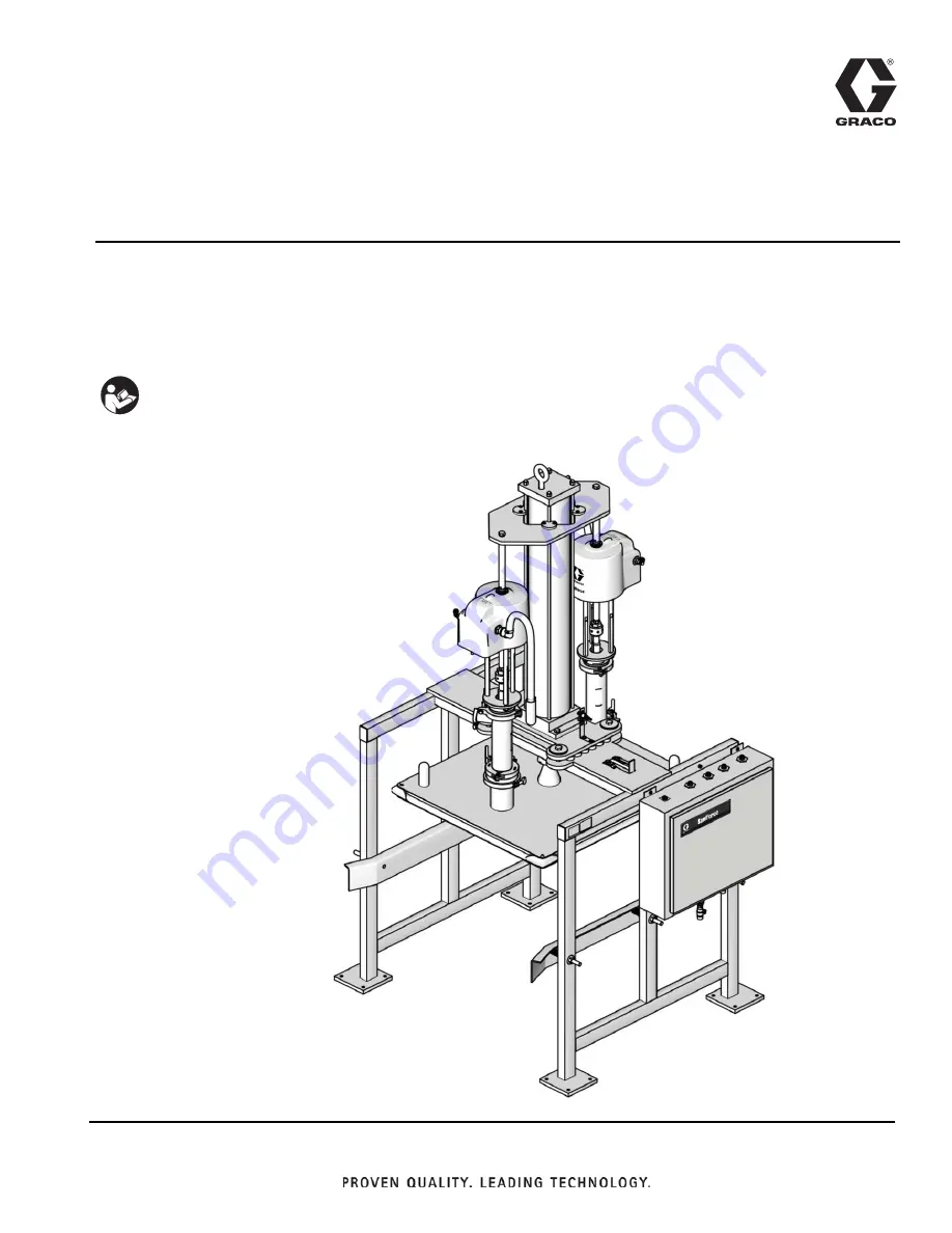
SaniForce

Bin Evacuation System

For use with 300 gallon (1135 liter) bags in bin containers. For professional use only. 
Not approved to European Explosive Atmosphere requirements.

See page 3 for model information, including maximum working pressure and approvals.

Important Safety Instructions

Read all warnings and instructions in this 

manual. Save these instructions.

Model BESE1A Shown

ti16236a

Summary of Contents for SaniForce BES Series

Page 1: ...bin containers For professional use only Not approved to European Explosive Atmosphere requirements See page 3 for model information including maximum working pressure and approvals Important Safety Instructions Read all warnings and instructions in this manual Save these instructions Model BESE1A Shown ti16236a ...

Page 2: ...m Plate and Seal 29 Troubleshooting 30 Service 31 Before Servicing 31 Replacing Cylinder Bearing All Models 31 Replacing Ram Plate Seal or Corner Seals All Models 32 Replacing Proximity Switch Electronic Control Models Only 33 Electronic Control Panel Service Electronic Control Models Only 33 SaniForce BES Pump Matrices 34 3150 AODD Pumps 34 Available Configurations 34 Pumps 35 Available Configura...

Page 3: ...7C 410 2 8 28 3 24G742 2 5 1 SaniForce Pump Manual 2 BESAAC 410 2 8 28 3 24G742 2 5 1 SaniForce Pump Manual 2 BESB7D 410 2 8 28 3 24G742 4 5 1 SaniForce Pump Manual 4 BESCCC 410 2 8 28 3 24P829 2 5 1 SaniForce Pump Manual 2 BES3F3 120 0 84 8 4 24C124 2 3150 SaniForce Pump 3A Ball Check Manual 2 BES3P3 120 0 84 8 4 248273 2 3150 SaniForcePump Ball Check Manual 2 BES4P3 120 0 84 8 4 248274 2 3150 Sa...

Page 4: ...Models 4 311163ZAH ...

Page 5: ...ide of grounded pail when triggering into pail If there is static sparking or you feel a shock stop operation immediately Do not use equipment until you identify and correct the problem Keep a working fire extinguisher in the work area ELECTRIC SHOCK HAZARD This equipment must be grounded Improper grounding setup or usage of the system can cause electric shock Turn off and disconnect power at main...

Page 6: ...s Do not kink or over bend hoses or use hoses to pull equipment Keep children and animals away from work area Comply with all applicable safety regulations MOVING PARTS HAZARD Moving parts can pinch cut or amputate fingers and other body parts Keep clear of moving parts Do not operate equipment with protective guards or covers removed Pressurized equipment can start without warning Before checking...

Page 7: ...S 1 The operator places the bin inside the frame 2 Using the control panel the operator lowers the ram plate on top of the material 3 The operator aligns and centers the bin with the ram plate 4 The operator inflates the ram plate seal applies down pressure to the ram plate and turns on the pumps 5 The pumps evacuate the material out of the bin 6 The operator stops the pumps deflates the seal and ...

Page 8: ... C Air Shutoff Valve shuts off air to the pneumatic control panel B D Sanitary Pumps pump material from the bin to the target application E Air Cylinder raises and lowers the pumps and the ram plate in and out of the material container F Ram Plate applies an even amount of pressure to the material in the bin When the ram plate seal is inflated it creates a seal The ram plate presses down on the ma...

Page 9: ...nitary Pumps pump material from the bin to the target application E Air Cylinder raises and lowers the pumps and the ram plate in and out of the material container F Ram Plate applies an even amount of pressure to the material in the bin When the ram plate seal is inflated it creates a seal The ram plate presses down on the material in the bin to assist the pumps in delivering the material FIG 2 T...

Page 10: ...rklift or pallet jack hand truck Provides easy and safe access to the air supply shutoff valves and the pneumatic control panel Graco recommends a minimum of 3 ft 0 91 m of open space in front of the panel Provides enough overhead clearance 11 ft 3 4 m recommended for installing and servicing the air cylinder and connecting air supply lines to the pneu matic control panel Has a flat level floor Mo...

Page 11: ...ion on top of the frame 602 See FIG 3 2 Lower the air cylinder shaft A through the center hole in the frame 3 Secure the air cylinder 4 to the frame 602 with the screws 20 and washers 19 See FIG 4 4 Install the air motor mounting plate 402 slipping plate over the top and down the length of air cylinder 4 5 Using tubing 6 connect the cylinder upper air sup ply line to the upper 1 2 in elbow 26 6 Us...

Page 12: ... two connecting rods 404 to the ram plates Secure with screws 405 and wash ers 411 13 Install cylinder guide bearings 408 on top of the air motor mounting plate 402 using screws 409 and washers 410 NOTE The open arch in the cylinder guide bearings 408 fits around tie rods on the air cylinder 4 14 Tighten lock nuts 7 15 Using tubing 6 connect pneumatic control panel to air motor air inlets 16 On th...

Page 13: ...e freely without kinking when the pumps move up and down The two pump AODD systems do not include a hose clamps or gaskets on the outlet side Two Pump System Includes Four Pump System Includes BESAxx BESBxx BESCxx BESExx BESFxx Qty 2 in 51 mm tri clamp sanitary clamps 412 2 or 3 2 in 51 mm tri clamp sanitary gaskets 413 2 or 3 BESDxx 1 5 in 38 mm tri clamp sanitary clamps 412 2 1 5 in 38 mm tri cl...

Page 14: ...s Dispense valve ground through connection to a prop erly grounded fluid hose and pump Fluid supply container follow your local code Solvent pails used when flushing follow your local code Use only conductive metal pails placed on a grounded surface Do not place the pail on a noncon ductive surface such as paper or cardboard which interrupts grounding continuity To maintain grounding continuity wh...

Page 15: ... the frame NOTE Follow any national and state lockout tagout codes and local regulations Disengaging 1 Make sure plate is raised all the way up not resting on stop 2 Move latch to Disengage position See FIG 8 The overall system weighs about 2400 3400 lb 1089 1542 kg To avoid injury always set manual stop latch to Engage position when working under the plate FIG 8 Manual Stop BESA7A shown Engage Po...

Page 16: ...ps E Pump Pressure Gauge Displays current pump pressure F Pump Pressure Regulator Adjust to raise or lower pump inlet air pressure G Ram Directional Switch Switch to UP to raise the ram plate Switch to DOWN to apply ram pressure to the material Switch to NEUTRAL to hold the position of the ram plate H Ram Up Pressure Gauge Displays Ram Up operation pressure J Ram Up Regulator Adjust to raise or lo...

Page 17: ...stroke and an air pocket forms in the material after the pump change over If pump cavitation occurs increase the ram down air pressure 10 Adjust the seal vacuum pump air regulator to 15 psi 103 kPa 1 0 bar 11 Deflate the seal 12 Press the RAM UP button If the ram does not raise increase the ram up air regulator pressure 13 Verify the seal is completely deflated after the ram plate exits the bin If...

Page 18: ...guides equally with the screws on all four sides of the bin Leave enough space between guides and bin to allow for removal of the bin 9 Make sure the corner seals 21 are in place 10 Use corners 39 to help guide the plate See FIG 10 11 Switch to the Ram Down position 12 Use the ram plate handles to center the ram plate inside the bin Be careful not to pinch the inflatable seal when it enters the bi...

Page 19: ...ly Pump 1 Supplies air to pump 1 G Pump 2 Air Supply Pump 2 Supplies air to pump 2 H Pump 3 Air Supply Pump 3 Supplies air to pump 3 J Pump 4 Air Supply Pump 4 Supplies air to pump 4 Bottom Panel Connections Pneumatic Source Connections B Air Controls Air Inlet 1 2 in npt f Air Controls Air Supply Line Supplies air to open and close air valves A Pumps Air Inlet 1 in npt f Pumps Air Supply Line Sup...

Page 20: ...be done by a qualified electrician and comply with all local codes and regulations Discrete Devices 110 VAC Manual Push Buttons Emergency Stop Power Manual Selector Switches Seal Inflate Pump Slow Pump Fast Digital Inputs 24 VDC Ram Jog Ram Up Start Stop High Speed Counter Flow meter sensor Ram Low Proximity switch 1 Seal Inflate PSI switch 1 Standard Functions Start Initiates pumping cycle Stop A...

Page 21: ... to select the ram operation mode H EMERGENCY STOP Press button to immediately shut off air to the system and stop operation J START Press button to begin operation K POWER Press button to enable power to the electronic control panel The air cylinder will stabilize in its current position FIG 12 Part No 15H145 and 15J902 Electronic Control 3 42 3 42 0RESET 0RESET 0RESET 0RESET 0RESET 0RESET 023 02...

Page 22: ...es the pumps to the slow mode operation for a user selected amount of time after which the pumps stop the seal deflates and the ram raises The system timer controls how long the pumps run at slow speed at the end of bin evacuation After the time elapses the controller stops the pumps deflates the seal and raises the ram up NOTE See Setting the Bin Empty Timer and Setting the Vacuum Pump Timer page...

Page 23: ...pressures as shown in the table below Make adjustments as needed during operation See FIG 14 Ref Function Regulator Setting psi kPa bar A SEAL INFLATE 15 103 1 0 Max B RAM UP 30 207 2 1 C RAM DOWN 30 207 2 1 D PUMP 1 50 345 3 4 E PUMP 2 50 345 3 4 F PUMP 3 50 345 3 4 G PUMP 4 50 345 3 4 H SEAL VACUUM 20 138 1 4 Four pump systems only FIG 14 Part No 570193 4 pump shown A B C D E F G H ti19841a ...

Page 24: ...access the timer screens Continue to toggle the key until the PUMP SLOW TIMER screen appears 2 Press the Enter key to enable numerical entry 3 Enter the desired set point Minimum Value 000 Maximum Value 999 Example 300 30 sec 4 Press the Enter key a second time to accept the value Setting the Bin Empty Timer The bin empty timer controls the amount of time the pumps operate at the slow speed for em...

Page 25: ... The batch mode will allow the user to control the operation of the ram unit flow meter output or pump stroke monitors Additional equip ment is required to operate in either of the batch modes For 15H145 and 15J902 controllers the batch mode is factory set to BATCHING DISABLED Refer to Electri cal Control Box manual shipped with the unit ...

Page 26: ... by using clamps 37 and tubes 38 See FIG 15 6 Load the bin of material into the center of the frame 7 Initial Startup Only The frame has spring loaded guides to stabilize the bin Adjust the guides equally with the screws on all four sides of the bin Leave enough space between guides and bin to allow for removal of the bin 8 Make sure the corner seals 21 are in place 9 Use corners 39 to help guide ...

Page 27: ...al deflates and the ram is raises Unloading the Bin 1 Follow the Pressure Relief Procedure page 24 2 Ensure seal is deflated and ram is raised 3 Unload the bin from the frame System Shutdown Follow the Pressure Relief Procedure page 24 Depending on the type of material it may be best to deflate the seal and raise the ram plate out of the mate rial or keep the ram plate lowered in the bin Some mate...

Page 28: ...ving material dry and build up and possibly contaminate new material or cause blockages Flush at the lowest pressure possible Check con nectors for leaks and tighten them if necessary To flush the system 1 Load a bin containing water compatible solvent or cleaning solution that can dissolve the material and clean the system Follow the procedure for Loading the Bin page 18 or page 27 NOTE Use solve...

Page 29: ...l and corner seals from the ram plate 5 Clean the seals and ram plate with a compatible cleaning fluid 6 Apply a generous amount of lubricant to the ram plate channel and seals 7 Install the inflatable seal and corner seals on the ram plate Position the inflatable seal so that the seal bottom is angled into the ram plate channel To avoid injury always set manual stop latch to Engage position when ...

Page 30: ...nd adjust until you have a quality seal Refer to troubleshooting in pump manual Material bag was sucked into pump Shut off air to pumps deflate seal and raise ram to clear pump intake Premature seal wear SEAL and RAM DOWN air pressures are too high Adjust SEAL and RAM DOWN air pressures until you have proper seal and pump operation Do not over pressurize the seal Material leaking past seal RAM DOW...

Page 31: ...washers 410 then take cylinder guide bearings 408 off the air motor mounting plate 402 3 Install cylinder guide bearings 408 on top of the air motor mounting plate 402 using screws 409 and washers 410 NOTE The open arch in the cylinder guide bearings 408 fits around tie rods on the air cylinder 4 4 Repeat steps 2 3 as needed to replace additional cylinder bearings 5 Raise and lower the ram plate t...

Page 32: ...and replace if necessary 3 Disconnect the tube fitting 29 from the seal air supply tube 14 4 Remove the ram plate seal 501 using a blunt end tool to avoid damaging the seal Carefully disen gage the air stem from the hole in the ram plate 502 5 Insert the air stem of the new seal 501 into the ram plate 502 hole To avoid puncturing the new seal carefully slide the seal in place around the ram plate ...

Page 33: ...ace between switch and plate 15 3 Disconnect the cable from the switch 641 4 Remove the two screws lock washers and the switch 5 Secure the new switch to the bracket B with the screws and lock washers 6 Reconnect the cable 7 Restart the system and verify the switch operates correctly Electronic Control Panel Service Electronic Control Models Only Follow the Before Servicing procedure page 31 Con s...

Page 34: ... require a configuration that is not listed Bin Evacuation System Pump Module see pages 38 45 Plate see page 46 Controls Frame see pages 46 56 B E S 3 SaniForce 3150 Ball Check 2 pumps A Arena 1 Electronic Controls Allen Bradley Micrologix 2 Pumps 4 SaniForce 3150 Flapper Check 2 pumps B Pallecon 3 Manual Controls 2 Pumps 8 SaniForce 3150 3A Design Ball Check 2 pumps F GoodPak MB5 P Plywood Model ...

Page 35: ...E Chep Iconic bin 2 pumps F Buckhorn bin 4 pumps Model Pump Plate Controls Frame BESA1F 5 1 2 pumps Arena Electronic Contrologix BESA4C 5 1 2 pumps Ceva Pallecon Manual BESAAC 5 1 2 pumps Buckhorn Manual BESA7A 5 1 2 pumps Plywood Electronic Micrologix BESA7C 5 1 2 pumps Plywood Manual BESA7F 5 1 2 pumps Plywood Electronic Contrologix BESB7B 5 1 4 pumps Plywood Electronic Micrologix BESB7D 5 1 4 p...

Page 36: ...st 4 20 513386 SCREW cap hex head 4 21 15F205 SEAL corner 4 22 551691 RIVET 3 8 in x 2 1 2 in sst 4 26 512684 FITTING elbow tube 2 28 107542 WASHER lock spring 4 29 112944 SCREW cap 7 32 070303 LUBRICANT GREASE 1 33 C78216 CLAMP ty rap 2 36 111265 LUBRICANT tube not shown 2 37 949412 CLAMP bag not shown not used with BESCCC 4 38 625988 TUBE wand not shown not used with BESCCC 4 39 626046 BIN corne...

Page 37: ...SET 0RESET 0RESET 1 1 3TROKE 3TROKE 3ET 5P 3ET 5P ACTOR ACTOR 5 5 4OTALIZER 4OTALIZER ETER ETER 3CREEN 3CREEN 0UMP S 0UMP S NABLE NABLE 3 7 3 7 3 3 2 50 2 50 34 24 34 24 34 0 34 0 54 54 05 0 05 0 34 34 4 4 2 02 33 2 02 33 2 2 34 0 34 0 0 7 2 0 7 2 2 2 R 19 17 18 16 15 7 13 7 12 10 11 26 6 33 4 53 28 47 40 21 14 29 22 See pages 38 45 See page 46 See page 46 See page 35 23 See page 47 45 44 Detail o...

Page 38: ...5 551365 SCREW hex hd 3 4 10 x 2 in 2 406 16D246 GASKET 6 in 2 407 16D245 CLAMP 6 in 2 408 625752 BEARING cylinder guide 4 409 104119 SCREW cap hex head 1 4 20 x 7 8 in 22 mm sst 8 410 170772 WASHER plain 8 411 551364 WASHER lock 3 4 in sst 2 412 500984 CLAMP 2 in tri clamp 2 413 512332 GASKET S clamp buna N 2 414 CLAMP for air motor drain hose not shown 2 415 16F384 FITTING air inlet 1 2 np x 1 2...

Page 39: ...ET 6 in 2 407 16D245 CLAMP 6 in 2 408 625752 BEARING cylinder guide 4 409 104119 SCREW cap hex head 1 4 20 x 7 8 in 22 mm sst 8 410 170772 WASHER plain 8 411 551364 WASHER lock 3 4 in sst 2 412 500984 CLAMP 2 in tri clamp 2 413 512332 GASKET S clamp buna N 2 414 CLAMP for air motor drain hose not shown 2 415 16F384 FITTING air inlet 1 2 np x 1 2 ptc 2 416 16A942 FITTING exhaust hose 2 423 101818 C...

Page 40: ...4 406 16D246 GASKET 6 in 4 407 16D245 CLAMP 6 in 4 408 625752 BEARING cylinder guide 4 409 104119 SCREW cap hex head 1 4 20 x 7 8 in 22 mm sst 8 410 170772 WASHER plain 8 411 551364 WASHER lock 3 4 in sst 4 412 500984 CLAMP 2 in tri clamp 4 413 512332 GASKET S clamp buna N 4 414 CLAMP for air motor drain hose not shown 4 415 16F384 FITTING air inlet 1 2 np x 1 2 ptc 4 416 16A942 FITTING exhaust ho...

Page 41: ...in 2 406 16D246 GASKET 6 in 2 407 16D245 CLAMP 6 in 2 408 625752 BEARING cylinder guide 4 409 104119 SCREW cap hex head 1 4 20 x 7 8 in 22 mm sst 8 410 170772 WASHER plain 8 411 551364 WASHER lock 3 4 in sst 2 412 118598 CLAMP 1 5 in tri clamp 2 413 16D169 GASKET buna N 2 414 CLAMP for air motor drain hose not shown 2 415 16F384 FITTING air inlet 1 2 np x 1 2 ptc 2 416 16A942 FITTING exhaust hose ...

Page 42: ...or module 24E441 1 403 15E477 SUPPORT pump 2 404 15K216 ROD tie 2 405 551364 ELBOW 1 2 14 npt m x 1 2 in 13 mm OD nylon 2 406 510490 TRI CLAMP 4 in 4 407 15H460 GASKET tri clamp 4 408 625752 BEARING cylinder guide 4 409 104119 SCREW cap hex head 1 4 20 x 7 8 in 22 mm sst 8 410 170772 WASHER plain 8 411 514334 WASHER lock 3 4 in sst 2 412 512684 NUT 3 4 10 Nylock 2 414 500263 ELBOW 3 4 14 npt x 1 5...

Page 43: ...2 406 510490 TRI CLAMP 4 in 4 407 15H460 GASKET tri clamp 4 408 625752 BEARING cylinder guide 4 409 104119 SCREW cap hex head 1 4 20 x 7 8 in 22 mm sst 8 410 170772 WASHER plain 8 411 551364 WASHER lock 3 4 in sst 2 412 512684 ELBOW 1 2 14 npt m x 1 2 in 13 mm OD nylon 2 414 500263 ELBOW 3 4 14 npt x 1 5 in 38 mm 304 stainless steel 2 415 171439 NIPPLE 1 11 5 npt x 3 4 14 npt 303 stainless steel 2...

Page 44: ...3 4 10 sst 2 406 16D246 GASKET 6 in Sanitary 2 407 16D245 CLAMP 6 in Sanitary 2 408 625752 BEARING cylinder guide 4 409 104119 SCREW cap hex head 1 4 20 x 7 8 in 22 mm sst 8 410 170772 WASHER plain 8 411 551364 WASHER lock 3 4 in sst 2 412 500984 CLAMP 2 in tri clamp 2 413 512332 GASKET S clamp buna N 2 414 CLAMP for air motor drain hose not shown 2 415 16F384 FITTING air inlet 1 2 np x 1 2 ptc 2 ...

Page 45: ...5 SCREW hex 3 4 10 sst 4 406 16D246 GASKET 6 in Sanitary 4 407 16D245 CLAMP 6 in Sanitary 4 408 625752 BEARING cylinder guide 4 409 104119 SCREW cap hex head 1 4 20 x 7 8 in 22 mm sst 8 410 170772 WASHER plain 8 411 551364 WASHER lock 3 4 in sst 4 412 500984 CLAMP 2 in tri clamp 4 413 512332 GASKET S clamp buna N 4 414 CLAMP for air motor drain hose not shown 4 415 16F384 FITTING air inlet 1 2 np ...

Page 46: ...0192 570193 15H145 249493 BESF9B 116464 16E396 570192 570193 15H145 249493 BESA4C 16A383 16E392 15E339 15E523 BESA7C 514984 16E391 15E339 15E523 BESAAC 514984 16M042 15E339 15E523 BESB7D 514984 16E397 570192 15M343 BESCCC 16X394 16U774 16U789 15E523 BES3F3 16D785 16D808 16D826 15E523 BES3P3 514984 15E348 15E339 15E523 BES4P3 514984 15E348 15E339 15E523 BES8B3 16A383 16A381 15E339 15E523 BESDBC 16D...

Page 47: ... GAUGE 160 PSI 4 6 VALVE check 3 8 in 2 7 VALVE air pilot 3 position 1 8 VALVE air pilot operated 1 9 SWITCH 3 position 1 10 REGULATOR 1 11 VALVE air pilot operated 1 12 16V728 SWITCH pneumatic 2 position 2 13 FITTING bulkhead 3 4 in NPT 1 14 FITTING bulkhead 3 8 in tube 1 15 FITTING bulkhead 1 2 in tube 2 16 MUFFLER 1 2 in NPT 2 17 TUBE 1 2 in O D AR 18 TUBE 3 8 in O D AR 19 TUBE 5 32 in O D AR 2...

Page 48: ...rols 48 311163ZAH Part No 15E523 2 Pump Manual Control Panel Pneumatic Diagram AIR IN PUMP 1 PUMP 2 SEAL RAM UP RAM DOWN SCHEMATIC S2 S3 T3 T3 T3 T3 R2 R5 R6 G5 G2 R1 G1 V4 R3 R4 G4 G3 V3 S1 V5 T2 T1 T1 T1 T1 T1 T1 F1 F2 F3 F4 F5 F6 M1 M2 ...

Page 49: ...ATOR air 1 2 in ports 4 REGULATOR air 0 25 psi 5 GAUGE 0 100 psi 6 GAUGE 0 30 psi 7 SWITCH 3 position 8 SWITCH 2 position 9 PUSH BUTTON momentary 10 VALVE air 3 way 11 BRACKET switch 12 BULKHEAD 1 2 npt FBE 13 BULKHEAD 1 2 npt f x 1 2 tod 14 BULKHEAD 1 4 npt fbe 15 BULKHEAD brass 3 4 npt 16 MUFFLER 1 2 npt 17 GAUGE 0 160 psi 18 VALVE 2 position 3 port 19 16F637 LABEL 20 17B758 LABEL instructions R...

Page 50: ...Inflatable Seal Plate Frames and Controls 50 311163ZAH Part No 15M343 4 Pump Manual Control Panel Pneumatic Diagram ...

Page 51: ... 119 120 62 Detail C Detail E Detail H Detail F 46 Detail A 22 51 40 37 37 71 116 36 38 63 38 42 116 36 56 42 38 37 71 Detail J 33 122 Detail A 67 24 25 26 Detail B 85 84 86 83 87 110 111 Detail G 42 9 Detail C E page 55 Detail F H page 56 Detail K 949949_2 121 Detail J Detail B Detail K ti10507b ti10517b 71 34 34 63 37 84 ...

Page 52: ... f 1 62 599248 FITTING tee 1 2 in tube x 1 2 nptm 3 63 599246 FITTING tee 1 4 in tube x 1 4 npt 3 65 510220 VALVE air 4 way 1 4 npt 3 66 501014 ACTUATOR air 1 8 npt 3 67 100721 PLUG pipe 1 4 nptf 11 68 156823 UNION swivel 1 4 npt 2 69 598141 FITTING tee air 5 32 x 1 8 npt 2 70 103831 SCREW 10 32 UNF 4 71 512912 MUFFLER polyethylene 3 72 158683 ELBOW 90 1 2 x 1 2 npt 3 73 551143 PUMP vacuum 1 74 10...

Page 53: ...2 Detail K 98 119 120 22 51 Detail J Detail E Detail D Detail H Detail F Detail G Detail A Detail B 40 37 71 42 38 37 71 Detail J Detail K Detail A 67 42 9 24 25 26 Detail B 85 84 86 83 87 46 Detail C E page 55 Detail F H page 56 570193_2 570193_3 570193_3 2 33 122 121 ti10506b ti10560b 84 116 36 38 63 38 42 116 36 56 63 37 37 34 71 ...

Page 54: ... 62 599248 FITTING tee 1 2 in tube x 1 2 nptm 4 63 599246 FITTING tee 1 4 in tube x 1 4 npt 5 65 510220 VALVE air 4 way 1 4 npt 5 66 501014 ACTUATOR air 1 8 npt 5 67 100721 PLUG pipe 1 4 nptf 15 68 156823 UNION swivel 1 4 npt 5 69 598141 FITTING tee air 5 32 x 1 8 npt 6 70 103831 SCREW 10 32 UNF 4 71 512912 MUFFLER polyethylene 3 72 158683 ELBOW 90 1 2 x 1 2 npt 3 73 551143 PUMP vacuum 1 74 100737...

Page 55: ...or 570193 and 949949 Pneumatic Control Panels Detail C 40 9 38 42 31 62 39 35 30 Detail D 72 36 73 38 42 9 55 74 31 56 30 Detail E 42 38 112 27 35 36 34 67 9 65 67 60 67 30 62 31 9 66 32 55 76 59 61 39 39 35 ti10499a ti10500a ti10494a ti10493a ti10496a ti10505a ti10497a ...

Page 56: ... Control Panels Detail F 67 67 68 35 31 39 63 66 69 42 65 59 69 55 81 40 60 32 42 59 36 34 Detail G 67 67 35 31 39 66 9 65 59 81 40 60 32 42 59 36 34 68 Detail H 67 29 25 24 42 115 27 112 79 80 76 28 63 26 56 68 ti10481a ti10483a ti10482a ti10484a 9 42 55 ti10485a ti10486a ti10488a ti10489a ti10491a ...

Page 57: ...9 Pneumatic Control Panel Pneumatic Diagram 94994902 4 3 4 9 4 0 36 36 36 36 06 06 04 2 3500 9 42 8 4 05 0 06 36 4 05 0 47 06 06 06 8 4 4 8 4 4 36 8 4 4 36 06 8 4 4 4 9 44 06 45 45 45 45 45 45 45 05 0 6 55 8 534 4 4 3 4 2 3500 9 45 2 3500 9 45 3 2 04 2 3500 9 05 0g3 AND ...

Page 58: ... EXH CONNECT TO 1 4 EXH CONNECT TO SV6 1 4 EXH CONNECT TO SV4 PV5 1 4 EXH CONNECT TO TO CYL BOTTOM PV4 5 32 TUBE 5 32 TUBE 5 32 TUBE 5 32 TUBE 5 32 TUBE 5 32 TUBE 5 32 TUBE INFLATE SEAL PUMP VACUUM 1 4 EXHAUST CONNECT TO ISOLATED AIR SUPPLY 1 2 TUBE AIR SUPPLY 1 4 TUBE SILENCER 1 NPT F AIR SUPPLY PUMP S 1 and 2 1 4 EXH CONNECT TO TO PUMP THREE PV2 TO PUMP FOUR PV1 1 4 EXH CONNECT TO PV1 PV2 RAM DO...

Page 59: ...ly Blue Blue F Ram Set Power Supply 14 Q1 Pump Slow Solenoid Red Red G Pump Slow Solenoid Q1 Q2 Pump Fast Solenoid Green Control Cable Green H Pump Fast Solenoid Q2 Q3 Ram Down Solenoid Orange Orange I Ram Press Solenoid Q3 Q4 Ram Up Solenoid Black white Color Code Black white J Ram Up Solenoid Q4 Q5 Ram Jog Solenoid White black White black K Ram Jog Solenoid Q5 Q6 Vacuum Pump Solenoid Green white...

Page 60: ...LIZER 4OTALIZER ETER ETER 3CREEN 3CREEN 0UMP S 0UMP S NABLE NABLE 3 7 3 7 3 3 2 50 2 50 34 24 34 24 34 0 34 0 54 54 05 0 05 0 34 34 4 4 2 02 33 2 02 33 2 2 34 0 34 0 0 7 2 0 7 2 2 2 R 10 in 254 mm 118 8 in 3 0 m 1 in 2 54 mm 20 in 51 m 20 in 51 m Front View Bottom View Front View Top View 15H145 and 15J902 Electronic Control System BESA7A Shown 58 3 in 1 48 m 69 in 1 75 m 60 in 1 52 m 50 6 in 1 28...

Page 61: ...11163ZAH 61 118 8 in 3 0 m Front View Top View System BES3F3 Shown 58 3 in 1 48 m 50 6 in 1 28 m 40 in 1 02 m 6 0 in 0 15 m 69 in 1 75 m 47 in 1 19 m 60 in 1 52 m ti16218a ti16219a 0 56 in 14 3 mm 4 holes per foot ...

Page 62: ...r 0 48 MPa Pump outlet 3 in tri clamp Sound data See your pump manual Wetted parts 300 Series stainless steel buna N and EPDM on the ram plate and seals See your pump manual for additional wetted parts Pneumatic Control Panel Maximum input air pressure 120 psi 8 4 bar 0 84 MPa Maximum up down ram pressure 75 psi 5 2 bar 0 5 MPa Air inlet air controls 3 4 in npt f Air inlet pump 1 2 in npt f Electr...

Page 63: ...gpm 104 5 lpm BESBxx 54 gpm 204 4 lpm BESCxx 27 6 gpm 104 5 lpm BESDxx 8 gpm 30 lpm BESExx 17 gpm 64 3 lpm BESFxx 34 gpm 128 7 lpm Pressure Ratio BESAxx BESBxx and BESCxx 4 3 1 BESDxx 6 1 BESExx and BESFxx 10 1 Air Consumption each pump BESAxx BESBxx and BESCxx 1 8 scfm per gpm 70 psi 0 14 m3 minute per lpm 4 8 bar 0 48 MPa BESDxx 6 scfm per gpm 70 psi 0 17 m3 minute per lpm 4 8 bar 0 48 MPa BESEx...

Page 64: ...in material or workmanship repairs will be made at a reasonable charge which charges may include the costs of parts labor and transportation THIS WARRANTY IS EXCLUSIVE AND IS IN LIEU OF ANY OTHER WARRANTIES EXPRESS OR IMPLIED INCLUDING BUT NOT LIMITED TO WARRANTY OF MERCHANTABILITY OR WARRANTY OF FITNESS FOR A PARTICULAR PURPOSE Graco s sole obligation and buyer s sole remedy for any breach of war...

Reviews: