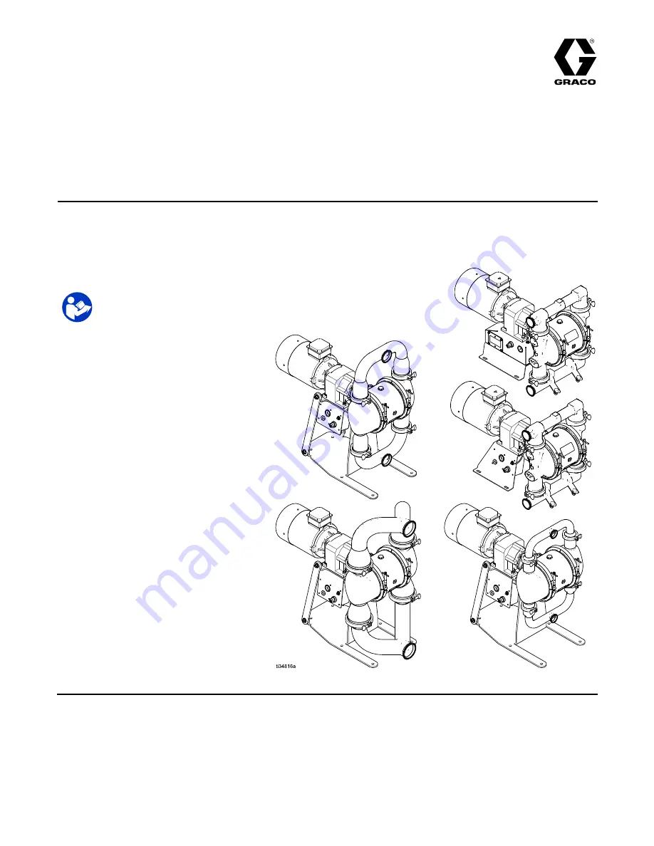
background image

Repair/Parts

SaniForce® 2150, 3000, 4000,
Electric - Operated

Diaphragm

Pump

3A5133J

EN

2

2

2---Inch,

Inch,

Inch, 3

3

3---Inch,

Inch,

Inch, and

and

and 4

4

4---Inch

Inch

Inch pumps

pumps

pumps with

with

with electric

electric

electric drive

drive

drive for

for

for fluid

fluid

fluid transfer

transfer

transfer applications.

applications.

applications.

Not

Not

Not approved

approved

approved for

for

for use

use

use in

in

in explosive

explosive

explosive atmospheres

atmospheres

atmospheres or

or

or hazardous

hazardous

hazardous locations

locations

locations unless

unless

unless otherwise

otherwise

otherwise stated.

stated.

stated. See

See

See

Approvals

Approvals

Approvals page

page

page for

for

for more

more

more information.

information.

information. For

For

For professional

professional

professional use

use

use only.

only.

only.

Important

Important

Important Safety

Safety

Safety Instructions

Instructions

Instructions

Read all warnings and instructions in this manual and in your
Operation manual. Save

Save

Save these

these

these instructions.

instructions.

instructions.

For maximum working pressure, see

Technical Data sheets

See page 7 for approvals.

PROVEN QUALITY. LEADING TECHNOLOGY.

Summary of Contents for saniforce 2150

Page 1: ...zardous hazardous hazardous locations locations locations unless unless unless otherwise otherwise otherwise stated stated stated See See See Approvals Approvals Approvals page page page for for for more more more information information information For For For professional professional professional use use use only only only Important Important Important Safety Safety Safety Instructions Instruct...

Page 2: ...ef Procedure 11 Check Valve Repair 11 Standard Diaphragm Repair 14 Overmolded Diaphragm Repair 16 Center Section Repair 18 Replace the Compressor 23 Parts 24 Kits and Accessories 33 Technical Data 34 Related Related Related Manuals Manuals Manuals Manual Number Title 3A5132 SaniForce 2150 3000 4000 Electric Operated Diaphragm Pump Operation 2 3A5133J ...

Page 3: ...ION EXPLOSION HAZARD HAZARD HAZARD Flammable fumes such as solvent and paint fumes in work work work area area area can ignite or explode Paint or solvent flowing through the equipment can cause static sparking To help prevent fire and explosion Use equipment only in well ventilated area Eliminate all ignition sources such as pilot lights cigarettes portable electric lamps and plastic drop cloths ...

Page 4: ...Turn off all equipment and follow the Pressure Pressure Pressure Relief Relief Relief Procedure Procedure Procedure when equipment is not in use Check equipment daily Repair or replace worn or damaged parts immediately with genuine manufacturer s replacement parts only Do not alter or modify equipment Alterations or modifications may void agency approvals and create safety hazards Make sure all eq...

Page 5: ... solvent manufacturer s Safety Data Sheet SDS and recommendations TOXIC TOXIC TOXIC FLUID FLUID FLUID OR OR OR FUMES FUMES FUMES HAZARD HAZARD HAZARD Toxic fluids or fumes can cause serious injury or death if splashed in the eyes or on skin inhaled or swallowed Read Safety Data Sheet SDS to know the specific hazards of the fluids you are using Store hazardous fluid in approved containers and dispo...

Page 6: ...ion Section Section Drive Drive Drive Type Type Type Center Center Center Section Section Section Material Material Material Gearbox Gearbox Gearbox and and and Compressor Compressor Compressor Motor Motor Motor 2150 2150 2150 T T T Food Grade E E E Electric A A A Aluminum 94 94 94 No Gearbox or Compressor A A A Standard Induction Motor 3000 3000 3000 HS HS HS High Sanitation S S S Stainless Steel...

Page 7: ...FK FK FK FKM Fluoroelastomer PT PT PT PTFE C21 C21 C21 2 1 certified S S S Stainless steel no manifolds CW CW CW Polychloroprene Weighted PS PS PS PTFE Santo prene 2 Piece C31 C31 C31 3 1 certified SSA SSA SSA Stainless Steel Tri Clamp HS 3 A PH FK FK FK FKM Fluoroelastomer PT PT PT PTFE EPDM 2 Piece SSB SSB SSB Stainless Steel DIN HS 3 A PH PT PT PT PTFE SP SP SP Santo prene EPDM 2 Piece SP SP SP...

Page 8: ... New New New Pump Pump Pump Please Please Please call call call your your your distributor distributor distributor OR OR OR Use the Online Online Online Diaphragm Diaphragm Diaphragm Pump Pump Pump Selector Selector Selector Tool Tool Tool at at at www graco com www graco com www graco com Search for Selector Selector Selector To To To Order Order Order Replacement Replacement Replacement Parts Pa...

Page 9: ...oose Tighten Pump cycles but will not prime and or pump Manifold o rings are damaged Replace o rings The center section is excessively hot The drive shaft is broken Replace Check valve balls seats or o rings are worn Replace Manifold screws or fluid cover screws are loose Tighten Pump fails to hold fluid pressure at stall NOTE NOTE NOTE Flapper checks are not 100 fluid tight Diaphragm shaft bolt i...

Page 10: ...hten Loose manifold screws or fluid cover screws Tighten Pump leaks fluid externally from joints Manifold o rings worn out Replace o rings A GFCI has tripped Remove the controller from the GFCI circuit Supply power is poor Determine and fix the source of the power problem The controller faults or shuts down Operational parameters are exceeded See performance chart ensure pump is operating within t...

Page 11: ...alls Also replace the o rings every time the manifold is removed Disassemble Disassemble Disassemble the the the Ball Ball Ball Check Check Check Valve Valve Valve 1 Follow the Pressure Relief Procedure page 11 Remove power from the motor Disconnect all hoses 2 Remove the clamps 31 holding the outlet manifold 3 to the fluid covers 2 then remove the outlet manifold 3 Remove the ball check valve ass...

Page 12: ...Repair 1 Arrow A must point toward outlet manifold 2 Radiused seating surface must face the ball 7 Large champfer on O D must face o ring 12 3A5133J ...

Page 13: ...ppers 7a and gaskets 8a 4 Repeat steps to remove the inlet manifold 4 Remove the flappers 7a and gaskets 8a To continue disassembly see Disassemble the Standard Diaphragms page 14 Reassemble Reassemble Reassemble the the the Flapper Flapper Flapper Check Check Check Valve Valve Valve 1 Clean all parts and inspect for wear or damage Replace parts as needed 2 Reassemble in the reverse disassembly or...

Page 14: ...pump 4 To remove the diaphragms the piston must be moved fully to one side If the pump is not attached to the gearbox turn the shaft by hand to move the piston If the pump is still attached to the gearbox loosen the screws and remove the fan cover Turn the fan by hand to rotate the shaft to shift the piston to one side TIP TIP TIP The air cover has 2 holes H one at the 9 o clock position and anoth...

Page 15: ...cking primer and allow it to dry 5 Apply medium strength blue thread locker to the threads of the bolt 6 Hold a 28 mm wrench on the wrench flats of the piston shaft Screw the bolt onto the shaft and torque to 100 ft lb 135 N m 7 Rotate the drive shaft to move the piston fully to one side See instructions in step 4 of Disassemble the Standard Diaphragms page 14 8 Repeat to install the other diaphra...

Page 16: ...emoving or installing diaphragm bolts a Hold a 28 mm wrench on the wrench flats of the exposed piston shaft Grip the diaphragm securely around the outer edge and rotate counterclockwise b Rotate the drive shaft to move the piston fully to the other side Repeat step 4a 5 To continue with disassembly see Disassemble the Center Section page 18 Reassemble Reassemble Reassemble the the the Overmolded O...

Page 17: ...4 of Disassemble the Overmolded Diaphragms page 16 8 Repeat to install the other diaphragm assembly 9 Attach the fluid covers 10 Reassemble the check valves and manifolds See Reassemble the Ball Check Valve page 11 11 Restore motor cooling fan cover and pin 131 to their original locations 1 Rounded side faces diaphragm 1 Piece 1 Piece 1 Piece EO EO EO Model Model Model 2 Apply medium strength blue...

Page 18: ... so the groove on the shaft is at the top in line with the alignment markings 7 Use a 3 4 16 bolt to push out the drive shaft assembly 112 You can also use the bearing bolt 106 but remove the bearing 107 first Be sure that the groove on the drive shaft remains aligned with the markings in the center section NOTE NOTE NOTE Remove the bolt after the drive shaft is freed NOTICE NOTICE NOTICE Proper a...

Page 19: ...ly anti seize lubricant on the mating edges of the drive shaft as shown in the illustration page 18 7 Center the piston in the housing and install the drive shaft assembly 112 into the center housing 101 with the groove facing up 8 Inspect the shaft coupler 113 for wear and replace if needed Install on the drive shaft 9 If removed install the alignment housing to the center section Apply medium st...

Page 20: ... center 4 Apply anti seize lubricant liberally on the radial surfaces of the drive shaft assembly 5 Install the drive shaft assembly with the groove facing up 6 Tighten screws in a crisscross pattern 5 turns at a time to engage the coupler evenly Torque to 130 160 in lb 15 18 N m 7 Apply lubricant to inner mating surface 20 3A5133J ...

Page 21: ... for ATEX or Flameproof motors Standard AC motors 04A 05A or 06A are of one piece with the gearbox so begin with step 3 NOTE NOTE NOTE Use a hoist and sling to remove motor weight from the gearbox during removal 1 Use a 3 4 in socket wrench to remove 4 screws 122 2 Pull the motor 121 straight off of the gearbox 118 3 Use a 3 4 in socket wrench to remove 4 bolts 17 and nuts 18 if present Lift the g...

Page 22: ...rom the VFD or other monitoring device f Apply air pressure to the pump and use a soapy solution around the bushing to ensure an air tight seal If air bubbles appear it will be necessary to return to the steps above for air pressure relief and removing the bushing from the pump Apply new thread sealer on the bushing and install in the pump so that the leak sensor is properly positioned Repeat this...

Page 23: ...4 Tip the pump on its side to provide access to the compressor box 5 Remove riser bracket 35 6 Remove the air line A1 from the compressor Disconnect the compressor wires at the terminal block L1 L2 and ground Remove the four bolts and carefully pull the compressor out of the box 7 Use the four bolts to install the new compressor Connect the air line from A1 to A1 as shown 8 Connect the wires from ...

Page 24: ...Parts Parts Parts Parts 2150T 2150T 2150T Pump Pump Pump 24 3A5133J ...

Page 25: ...Parts 2150HS 2150HS 2150HS Ball Ball Ball Check Check Check Pump Pump Pump 3A5133J 25 ...

Page 26: ...Parts 3000HS 3000HS 3000HS Flapper Flapper Flapper Pump Pump Pump 26 3A5133J ...

Page 27: ...Parts 4000HS 4000HS 4000HS Flapper Flapper Flapper Pump Pump Pump 3A5133J 27 ...

Page 28: ...34 26C244 Polychloroprene weighted CHECK VALVE flapper pkg of 4 1 25E582 3000HS 7a 25P086 4000HS O RING 4 15H831 PTFE 8 15H829 EPDM 8a GASKET sanitary EPDM kits are pkg of 4 4 Ref Ref Ref Part Part Part Kit Kit Kit Description Description Description Qty Qty Qty 15H459 25P063 3 in 2150HS 3 A PH 15H460 25P064 4 in 3000HS 17Z003 25P066 6 in 4000HS 9 189299 PLATE fluid side Stainless Steel 2 10 PLATE...

Page 29: ...s Ref 35a 1 35a 25B426 BOLT air compressor box M8 x 1 25 20mm 10 35b 17Z195 COVER air compressor box bottom 2150HS 3 A PH 3000HS 4000HS 1 Ref Ref Ref Part Part Part Kit Kit Kit Description Description Description Qty Qty Qty 38 25E384 CONTROL air with bracket 1 39 25E585 BASE mounting 1 39a 25E585 BRACE mounting 2 39b 25E585 SCREW flanged 4 39c 25E585 NUT lock 4 39d 25E585 WASHER 8 Not sold separa...

Page 30: ...Section Sample Configuration Number Pump Model Wetted Section Material Drive Center Section Material Gear Box and Motor Motor Fluid Covers and Manifolds Seats Balls Diaphragms Manifold Seals 2150 T E A A A 04 04 04 A S1 3 SS PT PT PT 30 3A5133J ...

Page 31: ...17 120 25B417 Aluminum Axx Axx Axx 116 25B418 Stainless steel Sxx Sxx Sxx 1 117 SCREW socket head M8 x 50 mm included with Ref 116 4 GEARBOX includes Ref 118a 118b 122 25B410 low speed 25B411 medium speed 118 25B412 high speed 1 Ref Ref Ref Part Part Part Description Description Description Qty Qty Qty 118a COUPLER included with Ref 118 1 118b KEY included with Ref 118 1 120 SCREW cap hex head M8 ...

Page 32: ...Through Through Diaphragm Diaphragm Diaphragm Kits Kits Kits For 2150T PT PT PT 25B451 SP SP SP 25B452 For all HS 3 A PH models FK FK FK 25P268 PS PS PS 25P266 SP SP SP 25B452 Kits include 2 diaphragms 11 2 backers 12 if applicable 1 packet anaerobic adhesive Overmolded Overmolded Overmolded Diaphragm Diaphragm Diaphragm Kit Kit Kit For all HS 3 A PH models EO EO EO 25P270 Kits include 2 diaphragm...

Page 33: ... Qty 25P084 SEAT flapper SP3F 2 45 25P085 SEAT flapper SP4F 2 25P065 GASKET EPDM SP3R 2 47 25P067 GASKET EPDM SP4F 2 15D475 CLAMP flapper SP3F 2 48 510490 CLAMP flapper SP4F 2 Dual Dual Dual Outlet Outlet Outlet 25P082 CHAMBER flapper SP3F 2 46 25P083 CHAMBER flapper SP4F 2 25P065 GASKET EPDM SP3R 2 47 25P067 GASKET EPDM SP4F 2 15D475 CLAMP flapper SP3F 2 48 510490 CLAMP flapper SP4F 2 Optional Op...

Page 34: ...in 66 0 mm 4000HS 4 in flapper 3 8 in 96 5 mm Minimum ambient air temperature for operation and storage NOTE NOTE NOTE Exposure to extreme low temperatures may result in damage to plastic parts 32 F 0 C Fluid displacement per cycle free flow 2150 0 6 gallons 2 3 liters 3000HS 4000HS 0 4 gallons 1 5 liters Maximum free flow delivery continuous duty 2150 100 gpm 378 lpm 3000HS 4000HS 60 gpm 227 lpm ...

Page 35: ...erage Load 7 68 A 230V 3 84 A 460V IE Rating IE3 AC ATEX 04C Power 7 5 HP 5 5 kW Number of Motor Poles 4 Pole Speed 1800 rpm 60 Hz or 1500 rpm 50 Hz Constant Torque 6 1 Gear Ratio 11 88 Voltage 3 phase 240V 3 Phase 415V Maximum Amperage Load 20 A 230V 11 5 A 460V AC ATEX 14C Power 5 0 HP 4 0 kW Number of Motor Poles 4 Pole Speed 1800 rpm 60 Hz or 1500 rpm 50 Hz Constant Torque 6 1 Gear Ratio 16 46...

Page 36: ...of 24D Power 3 0 HP 2 2 kW Number of Motor Poles 4 Pole Speed 1800 rpm 60 Hz or 1500 rpm 50 Hz Constant Torque 6 1 Gear Ratio 26 77 Voltage 3 phase 230V 3 Phase 460V Maximum Amperage Load 8 A 230V 4 A 460V Leak Leak Leak Sensor Sensor Sensor Contact Ratings State Normally closed Voltage 240V Max AC DC Current 0 28 A max at 120 VAC 0 14 A max at 240 VAC 0 28 A max at 24 VDC 0 07 A max at 120 VDC Po...

Page 37: ...s Wetted parts include material s chosen for seat ball and diaphragm options plus plus plus the the the pump s pump s pump s material material material of of of construction construction construction Aluminum Aluminum Aluminum Polypropylene Polypropylene Polypropylene Stainless Stainless Stainless Steel Steel Steel Conductive Conductive Conductive Polypropylene Polypropylene Polypropylene or or or...

Page 38: ... 390 177 557 253 433 196 407 185 599 271 509 231 500 227 299 136 Aluminum 358 162 326 148 306 139 473 215 349 158 323 146 515 234 425 193 416 189 215 98 2150HS 3 A PH Stainless Steel 440 200 408 185 388 176 555 252 431 195 405 184 597 271 507 230 498 226 297 135 Aluminum 365 166 333 151 313 142 480 218 356 161 330 150 522 237 432 196 423 192 222 101 3000HS Stainless Steel 447 203 415 188 395 179 5...

Page 39: ...ain chemicals will further limit the fluid temperature range Stay within the temperature range of the most restricted wetted component Operating at a fluid temperature that is too high or too low for the components of your pump may cause equipment damage Stainless Stainless Stainless Steel Steel Steel Pump Pump Pump Fluid Fluid Fluid Temperature Temperature Temperature Range Range Range Diaphragm ...

Page 40: ...RRANTY WARRANTY WARRANTY AND AND AND DISCLAIMS DISCLAIMS DISCLAIMS ALL ALL ALL IMPLIED IMPLIED IMPLIED WARRANTIES WARRANTIES WARRANTIES OF OF OF MERCHANTABILITY MERCHANTABILITY MERCHANTABILITY AND AND AND FITNESS FITNESS FITNESS FOR FOR FOR A A A PARTICULAR PARTICULAR PARTICULAR PURPOSE PURPOSE PURPOSE IN IN IN CONNECTION CONNECTION CONNECTION WITH WITH WITH ACCESSORIES ACCESSORIES ACCESSORIES EQU...

Reviews: