background image

32          308496

Troubleshooting

Spray Pattern Troubleshooting

NOTE: Some spray pattern problems are caused by the improper balance between air and fluid.

Problem

Cause

Solution

Fluttering or spitting spray

The fluid supply is insufficient.

Adjust the fluid regulator, or fill the
fluid supply.

The fluid nozzle is loose, or the fluid
nozzle taper seat is damaged.

Tighten or replace the fluid nozzle;
see page 36.

There is dirt between the fluid nozzle,
taper seat, and gun body.

Clean the parts; see page 24.

The coupler at the fluid inlet is loose
or cracked.

Tighten or repair the coupler.

There is fluid build-up on the air cap;
partially clogged horn holes; or full air
pressure from the clean horn hole
forces the fan pattern toward the
clogged end.

Clean the air cap with a soft imple-
ment or submerge it in water and
wipe it clean;  see page 24.

The electrode is bent.

Straighten the electrode.

The fluid nozzle or air cap holes are
damaged.

Replace the damaged part; see page
36.

There is fluid buildup on the perimeter
of the fluid nozzle orifice, or a partially
clogged fluid nozzle orifice.

Remove the obstruction; never use
wire or hard instruments; see page
24.

The electrode is bent.

Straighten the electrode wire.

The fan air pressure is too high.

Reduce the fan air pressure.

The fluid is too thin.

Reduce the fluid viscosity.

There is not enough fluid pressure.

Increase the fluid pressure.

The fan air pressure is too low.

Increase the fan air pressure.

The fluid is too thick.

Reduce the fluid viscosity.

There is too much fluid.

Reduce the fluid flow.

Streaks

The last coat of fluid is applied too
wet.

Apply a drier finish using multiple
strokes.

There is too much air pressure.

Decrease the air pressure.

The air pressure is insufficient.

Increase the air pressure.

The spray pattern is non-uniform.

Clean or replace the air cap; see
page 24.

Summary of Contents for PRO 5500wb

Page 1: ...t No 236824 Series A Includes the spray gun and shroud only Part No 238091 Series A Includes the spray gun shroud manifold regulator and mounting bracket NOTE The fluid hose must be ordered separately U S PATENT NO 4 290 091 4 219 865 4 497 447 4 462 061 4 660 774 5 063 350 5 073 709 5 080 289 5 093 625 5 289 977 Patented 1986 1987 Canada Brevete 1986 1987 U K PATENT NO 2 147 158 2 142 559B 2 140 ...

Page 2: ...Troubleshooting 32 Electrical Tests Test Gun Resistance 33 Test Power Supply Resistance 34 Test Resistor Stud Resistance 34 Service Tools Included with the Gun 35 Prepare the Gun for Service 35 Air Cap Nozzle Resistor Stud Replacement 36 Electrode Needle Replacement 37 Fluid Packing Rod Removal and Repair 38 Piston Repair 39 Barrel Removal 41 Power Supply Removal and Replacement 42 Turbine Alterna...

Page 3: ...covered by the conductive hose layer must be inside the voltage isolation system enclosure Refer to Fig 15 page 17 Only use the red colored Graco electrically conductive gun air hose with this gun Do not use the black or grey colored Graco air hoses Install only one continuous Graco waterborne fluid hose between the isolated fluid supply and the spray gun Do not splice hoses together Follow the Fl...

Page 4: ...nual Do not flush the system with the gun electrostatics turned on Use only non sparking tools to clean residue from the booth and hangers Extinguish all open flames or pilot lights in the spray area Keep the spray area free of debris including solvent rags and gasoline Do not store any flammable fluids in the spray area Do not turn on or off any light switch in the spray area while operating or i...

Page 5: ...Pa 7 bar maximum working air and fluid pressure Use fluids that are compatible with the equipment wetted parts See the Technical Data section of all the equipment manuals Read the fluid manufacturer s warnings Route the hoses away from traffic areas sharp edges moving parts and hot surfaces Do not expose Graco hoses to temperatures above 180 F 82 C or below 40 F 40 C Do not use the hoses to pull e...

Page 6: ... or purge the system Precautions must be taken when using electrostatic waterborne equipment to avoid potential shock haz ards When the spray gun charges the isolated fluid to high voltage it is similar to charging a capacitor or battery The system will store some of the energy while spraying and retain some of that energy after the spray gun is shut off It is not safe to touch the front end of th...

Page 7: ...ut D Shroud E Mounting Bracket F Manifold G Turbine H Power Supply J Electrode Manifold Markings A1 Atomization Air Inlet Fitting A2 Fan Air Inlet Fitting CYL Cylinder Air Inlet Fitting EXH PA Shroud Exhaust Outlet or Pilot Air Inlet Fitting F O Fiber Optic Fitting P1 Fluid Supply Inlet Fitting TA Turbine Air Inlet Fitting KV not used P2 not used ...

Page 8: ... your system is discharged The display modules will only display the system voltage while the guns power supply is operating Follow the Fluid Voltage Discharge and Grounding Procedure page 19 to ensure the system is discharged Graco Waterborne Fluid Hose purchased separately A Graco waterborne fluid hose must be used between the voltage isolation system fluid outlet and the spray gun fluid inlet T...

Page 9: ...e charged to high voltage must be contained within a fence or enclosure that prohibits personnel from making contact with the high voltage components before the system voltage is discharged The gun turbine air supply must be interlocked with the isolation system to shut off the turbine air supply anytime the isolation system enclosure or safety fence is opened The voltage isolation system must be ...

Page 10: ...enoid Valve requires quick exhaust port L Bleed type Air Shut off Valve M Air Pressure Regulator for fluid regulator pilot N True Earth Ground P Main Air Line Q Bleed type Master Air Valve R Shroud Exhaust Port for Gun P N 237603 or Pilot Air Line for Gun P N 238091 1 4 inch 6 4 mm O D S Check Valve T Fiber Optic Cable P N 224680 to 224686 U Bulkhead P N 189870 V Fiber Optic Cable P N 224670 to 22...

Page 11: ...es or on the skin The bleed type air shutoff valve is required on the fan and atomization air lines so trapped air will be relieved between the valve and the gun after the valves are closed 5 Install a check valve S in the pilot air line R to prevent fluid from backing up into the air controls Install the Gun and Mounting Bracket CAUTION To avoid electrical breakdown damage to the fluid regulator ...

Page 12: ...e air hose NOTE The hose and the gun have special left hand threads to prevent connecting another type of air hose to the gun turbine air inlet Manifold Connections See Fig 7 A1 Atomization Air Inlet Fitting Connect a 3 8 inch 9 5 mm O D tube between the fitting and the air supply A2 Fan Air Inlet Fitting Connect a 3 8 inch 9 5 mm O D tube between the fitting and the air supply CYL Cylinder Air In...

Page 13: ...ove the 1 8 npt plug 115 from the manifold s fiber optic port and install the black fiber optic fitting 124 See Fig 8 Fig 8 115 124 04305 2 Remove the nut EE from the fiber optic fitting 124 and slide the nut over the end of the fiber optic cable FF See Fig 9 3 Insert the cable FF into the fitting 124 and push the cable in until it bottoms out Tighten the nut EE to secure the cable Fig 9 EE FF 043...

Page 14: ...n from the manifold as instructed on page 35 2 Make sure the lens HH is clean Push the lens into the counterbore KK in the manifold fiber optic port GG See Fig 10 and 11 3 Press the lens retainer JJ into the manifold fiber optic port GG until it is flush with the manifold surface 4 Assemble the gun to the manifold as instructed on page 44 Fig 10 04484 HH JJ GG Fig 11 04485 JJ HH KK GG ...

Page 15: ...ipped and assembled to the dimensions shown in Fig 12 A new Graco waterborne fluid hose comes fully assembled to the proper dimen sions CAUTION Be careful not to cut into the inner hose layer K when stripping the hose Nicks or cuts in the tube will cause premature hose failure 2 Inspect the condition of the o rings G on the hose barbed fitting Replace the o rings if they are worn or damaged 3 Unsc...

Page 16: ...o about 55 in lb 6 2 N m Pull back on the hose to make sure it is secure CAUTION If the hose comes loose from the fitting fluid leakage will occur Make sure the nut L is tight and that nothing will pull or catch on the hose during opera tion 8 Check the gun s electrical grounding as instructed on page 18 9 Connect the other end of the hose as instructed in the voltage isolation system manual See F...

Page 17: ...r system must be connected to a true earth ground 1 Fluid Supply Ground the fluid supply by connect ing a ground wire and clamp between the fluid supply and a true earth ground See your fluid supply instruction manual for grounding instruc tions 2 PRO 5500wb Electrostatic Air Spray Gun Install the red colored Graco electrically conduc tive air hose between the gun and air supply line and connect t...

Page 18: ...stance should not exceed 100 ohms 5 If the resistance is greater than 100 ohms check the tightness of the ground connections and be sure the turbine air hose ground wire is connected to a true earth ground If the resistance is still too high replace the turbine air hose Fig 16 M N P Q 04307B Install the Fabric Cover Part No 237603 and 236824 Guns Only 1 Install a fabric cover AA over the front of ...

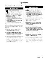
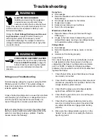
Page 19: ...tics are turned off or see Electrical Trouble shooting page 29 or the voltage isolation system manual for other possible problems Resolve the problem before proceeding Pressure Relief Procedure WARNING PRESSURIZED EQUIPMENT HAZARD The system pressure must be manually relieved to prevent the system from starting or spraying accidentally To reduce the risk of an injury from accidental spray from the...

Page 20: ...part no 193033 If your applica tion requires a different nozzle and air cap combina tion see instruction manual 307803 or consult your authorized Graco distributor to select the appropriate fluid nozzle and air cap Install the air cap and fluid nozzle into the gun barrel as instructed on page 36 Operating the Spray Gun WARNING FIRE AND EXPLOSION HAZARD To reduce the risk of fire and explosion only...

Page 21: ...5 bar air pressure to the cylinder air fitting CYL to trigger the fluid 5 Part No 237603 and 236824 Spray Guns Pres surize the fluid supply and adjust the fluid flow with the fluid pressure regulator installed in the fluid line Part No 238091 Spray Gun Set the fluid supply pressure to the gun at 70 to 80 psi 480 to 550 kPa 4 9 to 5 6 bar Control the fluid flow out of the gun by adjusting the air p...

Page 22: ...65 kPa 2 6 bar 50 ft 15 3 m 40 psi 280 kPa 2 8 bar 75 ft 22 9 m 42 psi 294 kPa 2 9 bar 100 ft 30 5 m 45 psi 314 kPa 3 1 bar 10 Check the voltage output of the gun using a high voltage probe and meter or by reading the ES kV Display Module NOTES The gun s normal high voltage reading is 45 to 55 kV due to spraying current demands and isolation system losses See Voltage Loss Troubleshooting on page 2...

Page 23: ...3 Clean the air cap and fluid nozzle daily minimum as instructed on page 24 Some applications require more frequent cleaning Replace the fluid nozzle and air cap if they are damaged See page 36 4 Check the electrode wire Straighten it if it is bent and replace it if it is broken or damaged See page 37 CAUTION Fluid in the air passages could cause the gun to malfunction and could draw current and r...

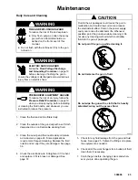
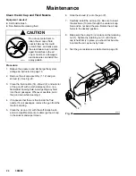
Page 24: ...id Avoid getting any fluid into the air passages Whenever possible point the gun down while cleaning it 4 If it appears that there is fluid inside the fluid nozzle 14 air passages remove the gun from the line for servicing 5 Clean the air cap 12 with the soft bristle brush and a compatible solvent or submerge the air cap in the solvent and wipe it clean 6 Slide the shroud 2 onto the gun P 7 Carefu...

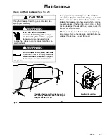
Page 25: ...tructed to relieve the pressure During operation periodically check the manifold exhaust tube N and both ends of the gun shroud Q for the presence of fluid Fluid in these areas would indicate fluid leakage into the shroud which could be caused by leaks at the fluid tube connections or fluid packing leakage If an air pilot line is used check it for the presence of fluid also If fluid is seen in any...

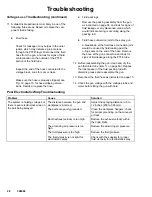
Page 26: ... causes include the following Spray Gun Fluid leakage Dielectric breakdown at the fluid hose connection or fluid packings Not enough air pressure for the turbine Faulty power supply Excessive overspray on gun surfaces Fluid in the air passages Waterborne Fluid Hose Dielectric failure of hose pin hole leak through PTFE layer Air gap in the fluid column between the gun and isolated fluid supply caus...

Page 27: ...the voltage isolation system NOTE Avoid allowing any water to leak out of the fluid hose as that could cause a significant air gap in the fluid column up to the gun electrode which can break the conductivity path and conceal a potential failure area 4 Position the end of the hose as far as possible away from any grounded surface The end of the hose must be at least 1 ft 305 mm from any ground Make...

Page 28: ...ring seals on the end of the hose Remove the hose at the gun connection and look for signs of fluid leakage along the PTFE tube 12 Before reassembling the gun clean and dry the gun fluid inlet tube item 17 on page 50 Repack the inner spacer of the fluid packing rod with dielectric grease and reassemble the gun 13 Reconnect the fluid hose as instructed on page 15 14 Check the gun voltage with the v...

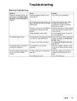
Page 29: ...x the problem Purge the air out of the fluid line Voltage isolation system failed See the isolation system manual for service information The operator gets a shock The operator is not properly grounded or is near an ungrounded object Be sure the floor and the operator are properly grounded see Ground the System page 17 The gun is not properly grounded See Check the Electrical Ground ing page 18 Th...

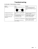
Page 30: ...r Excessive spray fog The air pressure is too high Reduce the air cap air pressure by decreasing the gun air inlet pressure use the least air pressure needed for good results The fluid is thinned too much Properly thin the fluid No fluid sprays from the gun The fluid supply is low Check the fluid supply add fluid if necessary The fluid nozzle is dirty or clogged Clean the fluid nozzle see page 24 ...

Page 31: ... The o rings on the piston stem are worn Inspect the o rings replace them as needed see page 39 Air leakage from the manifold The manifold gasket is damaged or the manifold is not tight Replace the gasket or tighten the manifold screws see page 44 Fluid leakage at the quick disconnect The manifold is not tight Tighten the manifold screws The fluid hose is not seated properly Make sure the hose was...

Page 32: ...ipe it clean see page 24 The electrode is bent Straighten the electrode The fluid nozzle or air cap holes are damaged Replace the damaged part see page 36 There is fluid buildup on the perimeter of the fluid nozzle orifice or a partially clogged fluid nozzle orifice Remove the obstruction never use wire or hard instruments see page 24 The electrode is bent Straighten the electrode wire The fan air...

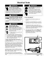
Page 33: ...mance of the spray gun is directly affected by the condition of the electrical components contained inside the gun The electrical tests can be used to determine the condition of the power supply and the resistor stud as well as the continuity of the electrical path between the components Use megohmmeter L part no 241079 and an ap plied voltage of 500 volts to complete these electrical tests Connec...

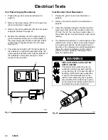
Page 34: ...ge 35 2 Remove the resistor stud 15 as instructed on page 36 3 Check the resistance between the black resistor stud ring contact S and the needle contact ring T See Fig 24 You may have to press down on the contact ring S in several places to get a good reading 4 The resistance should be 21 to 29 megohms If the resistance is correct make sure the metal contact in the gun barrel and the needle conta...

Page 35: ...or until after following the Fluid Voltage Discharge and Grounding Proce dure WARNING PRESSURIZED EQUIPMENT HAZARD To reduce the risk of an injury follow the Pressure Relief Procedure on page 19 before checking or servicing the system and whenever you are instructed to relieve the pressure 1 Discharge the voltage as instructed on page 19 2 Flush the gun with a non flammable cleaning fluid 3 Reliev...

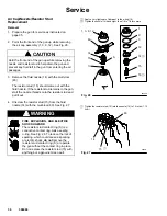
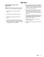
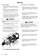
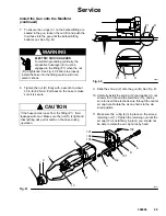
Page 36: ... resistor stud and pull it out 4 Unscrew the resistor stud 15 from the fluid nozzle 14 with the multi tool 83 See Fig 27 WARNING FIRE EXPLOSION AND ELECTRIC SHOCK HAZARD The resistor stud contact ring S is a conductive contact ring not a sealing o ring See Fig 26 To reduce the risk of sparking which could cause a sparking or electric shock do not remove the resistor stud contact ring S or operate ...

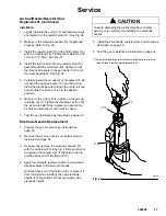
Page 37: ... is held firmly in place you should not be able to rotate the air cap horns by hand 7 Test the gun resistance as instructed on page 33 Electrode Needle Replacement 1 Prepare the gun for service as instructed on page 35 2 Remove the air cap nozzle and resistor stud as instructed on page 36 3 Unscrew and remove the electrode needle 13 with the multi tool 83 See Fig 28 Be careful not to damage the co...

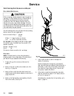
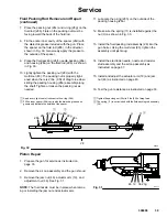
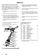
Page 38: ...0 x 8 80 The service interval would be 312 work days Procedure NOTE The fluid packing rod can be replaced as individual parts or as an assembly If the assembly is purchased it is pre adjusted at the factory 1 Prepare the gun for service as instructed on page 35 2 Remove the jam nut 46 and actuator arm 19 See Fig 31 page 39 3 Remove the air cap assembly fluid nozzle and resistor stud and electrode ...

Page 39: ...installed against the nut U as shown in Fig 30 13 Install the fluid packing rod assembly 28 into the gun barrel Using the multi tool 83 tighten the assembly until just snug 14 Install the electrode needle nozzle and resistor stud assembly and the air cap assembly as instructed on page 37 15 Install and adjust the actuator arm 19 and jam nut 46 as instructed on page 40 16 Test the gun resistance as...

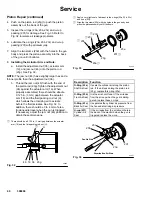
Page 40: ...air to actuate before the fluid actuates See Fig 32 In addition there should be 3 to 4 mm of elec trode needle travel when the gun is triggered If necessary adjust the jam nut 46 position to obtain these dimensions There should be a 0 125 in 3 mm gap between the actuator arm 19 and the fluid packing rod nut U Fig 32 04823 U 46 36 23g 19 Apply a very light coat of lubricant to the o rings 23a 23b 2...

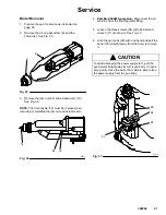
Page 41: ...m 04317 Fig 36 46 19 14 4 Part No 238091 Spray Gun Disconnect the air pilot line from the fluid regulator fitting 5 Loosen the three screws 24 with the ball end wrench 77 not shown See Fig 37 6 Hold the gun body 29 with one hand and pull the barrel 26 straight away from the body to remove it CAUTION To avoid damaging the power supply 27 pull the gun barrel straight away from the gun body If neces ...

Page 42: ...power supply free from the gun body 29 then pull it straight out See Fig 38 4 Inspect the power supply for any physical damage Check the electrical resistance as instructed in Test Power Supply Resistance page 34 If necessary replace the power supply 5 Before installing the power supply inspect the seal D for any damage or swelling Replace the seal if necessary Make sure the gaskets and pads 27a 2...

Page 43: ... to test the turbine alternator coil Measure the resistance between the two outer terminals of the 3 wire connector V Resistance should be 3 to 5 ohms If the reading varies from this value replace the alternator 6 Measure the resistance between each outer terminal of the 3 wire connector V and the alter nator 25 housing The resistance should be infinite If the resistance is not infinite replace th...

Page 44: ...18 Fig 39 26 24 20 27 27a 29 19 46 11 13 23g 36 17 Install the Gun onto the Manifold 1 Make sure the gaskets 121 108 and the spring 105 are on the manifold 101 See Fig 41 page 45 Inspect the parts for damage and replace as needed 2 Make sure the fluid hose PTFE tube A which inserts into the gun and the gun fluid tube 17 opening are clean If the parts are dirty clean them and apply a light coat of ...

Page 45: ...n the hose to make sure it is secure CAUTION If the hose comes loose from the fitting P1 fluid leakage will occur Make sure the nut D is tight and that nothing will pull or catch on the hose during operation ÇÇÇÇÇ ÇÇÇÇÇ Fig 40 P1 C D E D P1 05927 9 Slide the shroud 2 onto the gun B See Fig 41 10 Carefully install the air cap 12 and gasket 3 not shown Do not bend the electrode 13 and be sure to ins...

Page 46: ...barrel C and tighten the fitting securely Connect the air tubing 90 to the elbow fitting E Refer to Fig 43 8 Install the barrel on the gun body as instructed on page 44 9 Install the gun onto the manifold as instructed on page 44 Make sure the seat 408 is aligned with the regulator body 401 threads to avoid cross threading PTFE side of diaphragm 413 faces up toward body 401 Tighten the cover 402 f...

Page 47: ... 7 Install the tube fitting 89 into the adapter 88 8 Install the barrel on the gun body as instructed on page 44 9 Install the air tubing 90 between the regulator elbow fitting E and the tube fitting 89 Cut the tubing to the length needed 10 Install the gun onto the manifold as instructed on page 44 NOTE Use the parts drawing and list on pages 52 and 53 to order replacement parts for your gun afte...

Page 48: ... hose has a pin hole failure strip back the outer hose jacket H and the conductive layer J about 12 inches 105 mm on each hose end Look for the failure point which will be a very small pin hole discolored due to arcing Continue stripping back the hose until the failure point is found 5 Carefully cut through the outer hose jacket H and peel it back about 12 inches 105 mm Do not cut into the conduct...

Page 49: ...308496 49 Notes ...

Page 50: ...3g 75 See page 55 to order the parts 7 6 21 46 19 36 11 29 Item 23 includes 23a 23g Item 25 includes 25a and 25b Item 27 includes 27a 27f Item 28 includes 28a 28h 23a 23b 23c 23d 23f 23e 87 28a 28h 28c 28d 28e 0601 28f 28g REF NO 28 Packing Rod Assembly Includes items 28a 28h Part No 237603 and 236824 Spray Gun 04326B ...

Page 51: ... 3 25 222319 ALTERNATOR turbine Includes items 25a and 25b 1 25a 110073 O RING Viton 1 25b 185124 CUSHION 1 Ref No Part No Description Qty 26 223940 BARREL gun 1 27 237250 POWER SUPPLY ASSY 60 kV Includes items 27a 27f 1 27a 186840 GASKET 1 27b 185099 PAD 1 27c 185145 PAD 2 27f 192361 PAD 1 28 224747 PACKING ROD ASSY Includes items 28a 28h 1 28a 185495 HOUSING packing 1 28b 223981 ROD fluid 1 28c ...

Page 52: ... to order the parts 7 6 21 46 19 36 11 29 Item 23 includes 23a 23g Item 25 includes 25a and 25b Item 27 includes 27a 27f Item 28 includes 28a 28h 23a 23b 23c 23d 23f 23e 87 28a 28h 28c 28d 28e 0601 28f 28g REF NO 28 Packing Rod Assembly Includes items 28a 28h See page 46 to order the parts 89 88 90 Part No 238091 Spray Gun 05431B ...

Page 53: ...SHION 1 26 223940 BARREL gun 1 Ref No Part No Description Qty 27 237250 POWER SUPPLY ASSY 60 kV Includes items 27a 27f 1 27a 186840 GASKET 1 27b 185099 PAD 1 27c 185145 PAD 2 27f 192361 PAD 1 28 224747 PACKING ROD ASSY Includes items 28a 28h 1 28a 185495 HOUSING packing 1 28b 223981 ROD fluid 1 28c 185488 NUT packing 1 28d 186069 SPACER packing 1 28e 178763 PACKING rod 1 28f 178409 PACKING fluid 1...

Page 54: ...s Apply high strength green Loctite or an equivalent sealant to the threads Tighten the fitting until the hex bottoms against the manifold This fitting 113 has left hand threads Install the kV cap 111 flush to the outside surface An optional fiber optic fitting 31 is included with the gun assembly see page 51 Remove the plug 115 and install the fitting 31 if a kV display is being used Press fit th...

Page 55: ...113 186845 FITTING turbine 1 4 18 npsm left hand thread 1 114 107107 REGULATOR disk 1 115 112645 PLUG 1 8 27 npt 2 116 112646 PLUG 5 8 18 x 5 8 1 117 190220 NUT strain relief 1 118 190219 FITTING strain relief 1 119 290068 LABEL caution 1 120 290069 LABEL warning 1 121 190301 GASKET foam 1 These parts are included in Air Seal Repair Kit 236827 which may be purchased separately Optional gaskets are...

Page 56: ... Hoses for use with the Graco H2O PRO Voltage Block Bare PTFE fluid hoses without the ground shield See Manual 308688 for information on the hoses Fluid Hose Assy Part No Hose Length 238877 25 ft 7 6 m 238878 50 ft 15 2 m Hoses for use with Graco Fenced Isolation System Fluid Hose Assy Part No Hose Length 237548 25 ft 7 6 m 237549 36 ft 11 m 237550 50 ft 15 2 m Hoses for use with non Graco voltage...

Page 57: ... No Hose Length 235068 6 ft 1 8 m 235069 15 ft 4 6 m 235070 25 ft 7 6 m 235071 36 ft 11 0 m 235072 50 ft 15 2 m 235073 75 ft 23 0 m 235074 100 ft 30 5 m Fluid Regulator Conversion Kit 238147 To add a fluid regulator to the part no 237603 and 236824 PRO 5500wb spray guns See page 47 for kit installation instructions Gun High Voltage Probe Meter 217452 For direct measurement of the gun output voltag...

Page 58: ...per ASTM Standard D4206 Sus tained Burn Test Category Data Maximum Fluid Temperature 120 F 49 C Wetted Parts Stainless Steel Nylon Acetal PTFE Kalrez Ceramic Chemraz Fluoro polymer Maximum Noise Level with atomization air at 100 psi 0 7 MPa 7 bar and maximum air flow Sound Pressure Sound Power 101 5 Db A 107 0 Db A Sound pressure was measured per Cagi Pneurop 1969 The measurement was taken 3 28 fe...

Page 59: ...308496 59 Notes ...

Page 60: ...ranty shall be as set forth above The buyer agrees that no other remedy including but not limited to incidental or consequential damages for lost profits lost sales injury to person or property or any other incidental or consequential loss shall be available Any action for breach of warranty must be brought within two 2 years of the date of sale Graco makes no warranty and disclaims all implied wa...

Reviews: