Graco Monark A Series Instructions-Parts List Manual Download Page 9

9

307-043

Air Motor Service

7.

Pull the piston assembly (G) from the air motor
base (F), and set it aside.

8.

Remove the bearing housing assembly (26 or 27)
for all Models except Model 206–955. Remove and
wipe the seat clean with a cloth. For model
206–955, remove retainer ring (3) and bearing (4).
Remove seal (2, 27 or 28).

9.

Remove the base from the vise, and set it upright
on the workbench.

10. Place the piston rod flats in a vise.

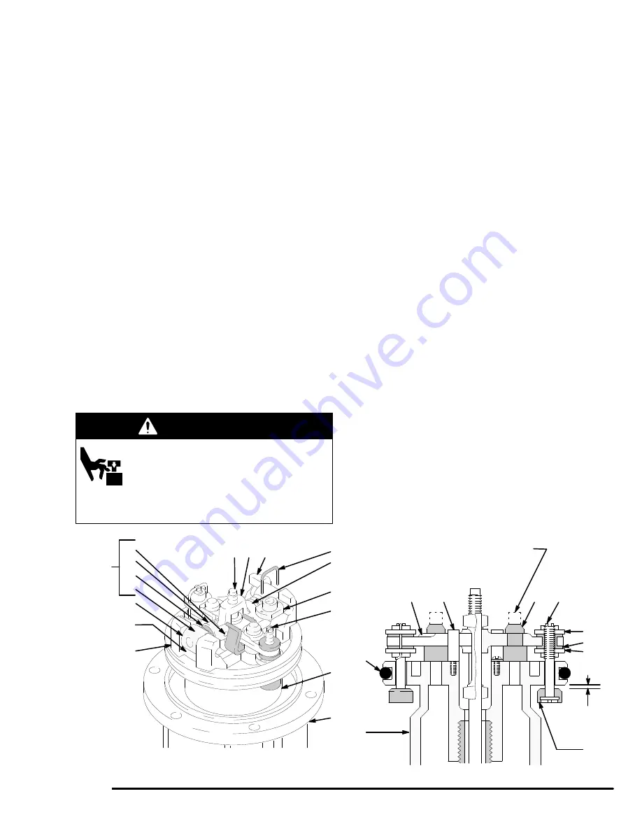
11. Use a screwdriver to push down on the trip rod

yoke (O), and snap the toggles down.  See Fig. 3.

WARNING

MOVING PARTS HAZARD
To reduce the risk of pinching or ampu-
tating your fingers, keep your fingers
clear of the toggle assemblies when you
are snapping the toggles (U in Fig. 3 ) up
or down.

12.

In this step, while you are prying with the screw

-

driver with one hand, cover the toggle assemblies
with your other hand so as to catch the spring-
loaded toggle assemblies when they snap out of
the lugs.  Place the tip of a screwdriver into the
piston between the piston lugs (P) below the pivot
pins (Q) on the toggles, pry up with the screw-
driver handle to compress the springs on the
toggle assembly (U) up and away from the piston
lugs, and remove the parts.  See Fig. 3.

13. Straighten the lockwires (L**) and remove them

from the upper valve nuts (J**).  Screw the upper
valve nuts off. Remove the trip rod yoke (O),
actuator (V), and trip rod (C).

14. Unscrew the bottom valve nuts (K**), and remove

the poppets (N**).  Make sure the valve bar spring
clips (W) are not worn or damaged and that they
properly guide the actuator (V).

15. Remove the exhaust valve poppets (M) by cutting

them with a side cutter, then pull them out of the
actuator (V).

16. Remove piston o-ring (Z) and internal base o-ring

(15** or 19**). Inspect o-rings.

17. Clean all the parts carefully in a compatible solvent

and inspect them for wear or damage.  Use all the
repair kit parts during reassembly, and replace
other parts as necessary.

18. Check the surfaces of the piston, piston rod, and

cylinder wall for scratches or wear.  A scored rod
will cause premature packing wear and leaking.

Fig. 3

04118

C O U

L

J

X

G

F

T

T

04119

W

V

G

M

X

J

K

N

0.145 in. 
(3.7 mm)

P

Q

S

R

Z

U

Y

Cutaway View

Cut off the tops of the poppets
as indicated by the dotted lines

Z

Insert Screw
Driver Here

Summary of Contents for Monark A Series

Page 1: ...g Pressure Model 204 237 Series M For in line mounting Model 206 955 Series G For stanchion tube mounting Model 205 997 Series G Model 215 363 Series A Model 945 972 Series A Model 222 791 Series A Fo...

Page 2: ...and labels before operating the equipment D Use the equipment only for its intended purpose If you are not sure call your Graco distributor D Do not alter or modify this equipment D Check equipment d...

Page 3: ...kly Refer to the gun manual Be sure the gun trigger safety operates before spraying Lock the gun trigger safety when you stop spraying Follow the Pressure Relief Procedure on page 8 if the spray tip n...

Page 4: ...including solvent rags and gasoline Electrically disconnect all equipment in the spray dispense area Extinguish all open flames or pilot lights in the spray dispense area Do not smoke in the spray di...

Page 5: ...in 146 1 mm Mounting Hole Layouts Three 0 34 in 8 6 mm diameter holes on 6 38 in 162 1 mm bolt circle 3 Tie Rod Pumps 05707 05708 45_ 45_ 2 5 in 64 mm 2 5 in 64 mm 4 in 102 mm 1 in 25 mm radius 161 3...

Page 6: ...45 cm2 Effective piston diameter 3 in 76 mm Stroke 3 in 76 mm Sound Data Sound Level at 180 psi 25 cycles min 96 dBa Sound Power at 180 psi 25 cycles min 112 dBa Air Valves Urethane Valve mechanism Ba...

Page 7: ...as shown in Fig 1 2 Air and fluid hoses use only electrically conductive hoses 3 Air compressor follow manufacturer s recommen dations 4 Fluid supply container according to local code 5 To maintain g...

Page 8: ...gs See Parts List on pages 12 14 For best results keep parts marked with one aster isk on hand to reduce down time Two accessory tools should be used Padded Pliers 207 579 are used to grip the trip ro...

Page 9: ...ins Q on the toggles pry up with the screw driver handle to compress the springs on the toggle assembly U up and away from the piston lugs and remove the parts See Fig 3 13 Straighten the lockwires L...

Page 10: ...e the toggle assembly U by placing a well greased spring onto the toggle arm T and then the toggle rocker S Place the toggle arm T ends of the toggle assembly U onto the toggle pins and snap the pivot...

Page 11: ...he base F CAUTION To avoid damaging the cylinder wall lower the cylin der straight down onto the piston Never tilt the cylinder as it is being lowered 16 Grip the trip rod C with padded pliers Remove...

Page 12: ...3 ARM toggle 2 14 160 624 O RING buna N 1 15 160 625 O RING buna N 1 16 160 896 STEM valve 2 17 160 932 GASKET copper 1 18 177 136 ROD piston 1 19 172 573 PLATE warning 1 20 169 627 NUT cap 1 21 169 6...

Page 13: ...KWIRE transfer valve 2 15 172 867 ACTUATOR valve 1 16 160 621 O RING nitrile rubber 1 17 160 623 ARM toggle 2 18 160 624 O RING buna N 1 19 160 625 O RING buna N 1 20 160 885 BASE 1 21 160 886 ROD pis...

Page 14: ...le rubber 1 13 160 623 ARM toggle 2 14 160 624 O RING buna N 1 15 160 625 O RING buna N 1 16 160 896 STEM valve 945 972 ONLY 2 17 160 932 GASKET copper 1 18 164 186 CYLINDER 1 19 167 585 SPRING helica...

Page 15: ...ENCER KIT 215 354 Fits Monark Air Motors Models 206 955 222 991 205 997 and 215 363 See Instruction Manual 307 361 GROUNDING WIRE 222 011 25 ft 7 6 m long 12 awg For grounding pump GAUGE 171 818 For a...

Page 16: ...l be as set forth above The buyer agrees that no other remedy including but not limited to incidental or consequential damages for lost profits lost sales injury to person or prop erty or any other in...

Reviews: