


5
684-027
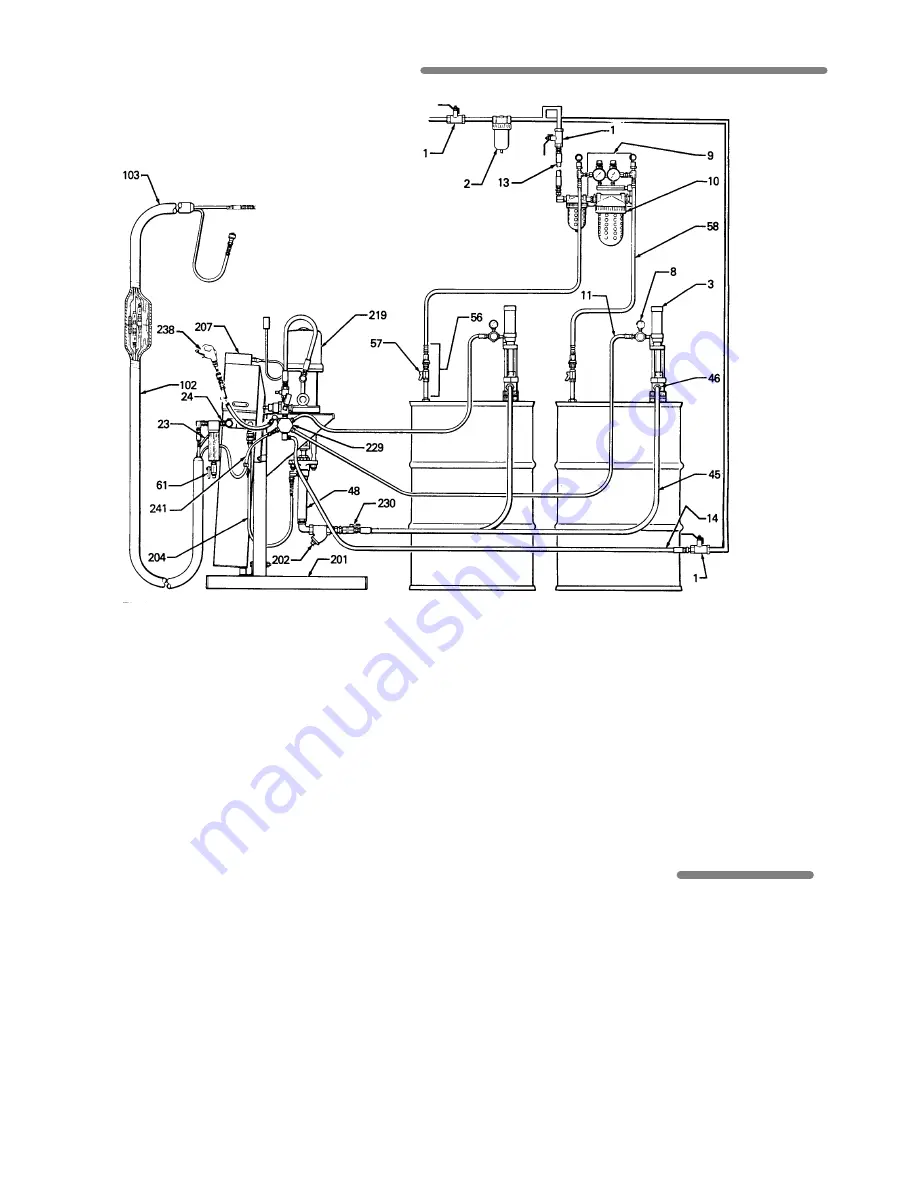
TYPICAL INSTALLATION DRAWING
The Typical Installation drawing above is only a
guide to show all the components and
recommended accessories for LX2000 Sprayer
Model 973-005, and the correct routing of all air and
fluid hoses. For assistance in getting up a system
to suit your needs, contact your Graco
representative.
LX2000 Sprayer Component Manuals
& Recommended Accessory Manuals
Manual No.
Description
306-989
Plural Component Pump
306-982
Air Motor
307-944
Displacement Pump
307-552
1:1 Ratio Feed Pumps
307-551
Pump Stand
308-219
Heater
307-544
Heated Hose
307-548
Air Dryer
307-692
Solvent Flush Kit
307-273
Fluid Filter
306-861
Check Valve
KEY
1
Master Air Valve
58 Dry Air Hose, Air Dryer
2
Air Line Filter
61 Drain Valve, Heater
3
Feed Pump
102 Heated Hose
8
Air Regulator or Air Valve
103 Heated Whip Hose
9
Air Dryer
201 Pump Stand
10
Air Dryer Ring
202 Y-Line Strainer
11
Air Hose, Feed Pump Kit
204 Fluid Hose, Disp Pump
13
Main Air Supply to Dryer
to heater
23
Control Box Cable, Heater
207 Heater
24
Fluid Outlet, Heater
219 Proportioning Pump
45
Feed Hose, Feed Pump to
229 Air Manifold
Disp. Pump
230 Intake Valve, Disp.
46
Fluid Outlet, Proportioning
Pump
Pump, (one of two)
238 Air Blow Gun
48
Displacement Pump
241 Main Air Supply to
56
Drum Fittings, Air Dryer
Hose
57
Shutoff Valve, Drum Fittings
242 Solvent Flush Kit
REFERENCE NUMBERS
Reference numbers in parentheses in the text refer
to the parts shown in the Typical Installation
drawing, Figures 1 thru 27, and/or the Parts
Drawing.
Parts information for reference numbers 1 thru 61
can be found in separate manuals accompanying
the sprayer or accessories.
Parts information for reference numbers 101 thru
243 can be found on page 16.


