


4
306-787
EQUIPMENT MISUSE HAZARD
General Safety
Any misuse of the spray equipment or accessories, such as
overpressurizing, modifying parts, using incompatible chemi-
cals and fluids, or using worn or damaged parts, can cause
them to rupture and result in fluid injection, splashing in the
eyes or on the skin, or other serious bodily injury, or fire, ex-
plosion or property damage.
Never alter or modify any part of this equipment; doing so
could cause it to malfunction.
Check all spray equipment regularly and repair or replace
worn or damaged parts immediately.
Always wear protective eyewear, gloves, clothing and respi-
rator as recommended by the fluid and solvent manufacturer.
System Pressure
Refer to the Technical Data on page 19 for specific fluid and
air working pressures. Never exceed the maximum fluid or air
working pressure. Be sure that all spray equipment and ac-
cessories are rated to withstand the maximum working pres-
sure of this sprayer. Do not exceed the maximum working
pressure of the lowest rated component or accessory used in
the system.
Fluid Compatibility
Be sure that all fluids and solvents used are chemically com-
patible with the wetted parts shown in the Technical Data on
page 19 and in the separate pump and component manuals.
Always read the manufacturer’s literature before using fluid or
solvent in this pump.
FIRE OR EXPLOSION HAZARD
Static electricity is created by the flow of fluid through the
pump and hose. If every part of the spray equipment is not
properly grounded, sparking may occur, and the system may
become hazardous. Sparking may also occur when plugging
in or unplugging a power supply cord. Sparks can ignite
fumes from solvents and the fluid being sprayed, dust parti-
cles and other flammable substances, whether you are
spraying indoors or outdoors, and can cause a fire or explo-
sion and serious bodily injury and property damage. Do not
plug in or unplug any power supply cords in the spray area
when there is any chance of igniting fumes still in the air.
If you experience any static sparking or even a slight shock
while using this equipment, stop spraying immediately.
Check the entire system for proper grounding. Do not use the
system again until the problem has been identified and cor-
rected.
Grounding
To reduce the risk of static sparking, ground the pump, object
being sprayed, and all other spray equipment used or located
in the spray area. Check your local electrical code for detailed
grounding instructions for your area and type of equipment.
Be sure to ground all of this spray equipment:
1.
Pump: use a ground wire and clamp as shown in Fig. 1.
2.
Air compressor: follow manufacturer’s recommendations.
3.
Air and fluid hoses: use only grounded hoses with a
maximum of 500 feet (150 m) combined hose length to
ensure grounding continuity. Refer also to HOSE SAFE-
TY.
4.
Spray gun: grounding is obtained through connection to
a properly grounded fluid hose and pump.
5.
Object being sprayed: according to your local code.
6.
Fluid supply container: according to your local code.
7.
All solvent pails used when flushing, according to local
code. Use only metal pails, which are conductive, placed
on a grounded surface. Do not place the pail on a non-
conductive surface, such as paper or cardboard, which
interrupts the grounding continuity.
8.
To maintain grounding continuity when flushing or reliev-
ing pressure, always hold a metal part of the spray gun
firmly to the side of a grounded
metal pail, then trigger
the spray gun.
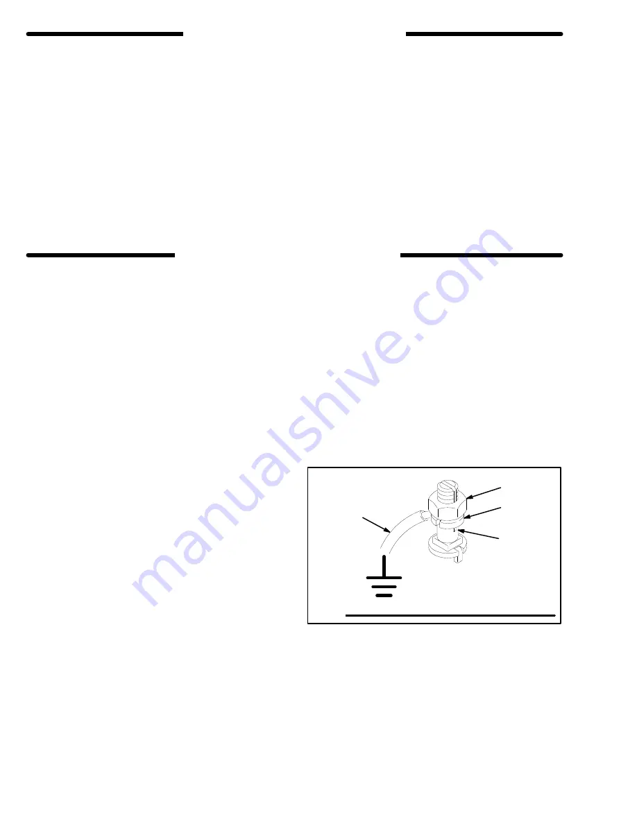
To ground the pump:
To ground the pump, loosen the grounding lug locknut (W)
and washer (X). Insert one end of a 1.5 mm
(12 ga) mini-
mum ground wire (Y) into the slot in lug (Z) and tighten the
locknut securely. See Fig. 1. Connect the other end of the
wire to a true earth ground. See Accessories on page 13.
Fig. 1
W
X
Y
Z
Flushing Safety
Before flushing, be sure the entire system and flushing pails
are properly grounded. Refer to Grounding, at the left. Fol-
low the Pressure Relief Procedure on page 3, and
remove
the spray tip from the spray gun. Always use the lowest pos-
sible fluid pressure, and maintain firm metal-to-metal contact
between the spray gun and the pail during flushing to reduce
the risk of fluid injection injury, static sparking and splashing.
Summary of Contents for Hydra-Spray 224-621
Page 18: ...18 306 787 Notes ...


