


WARNING
To reduce the risk of serious bodily injury, in-
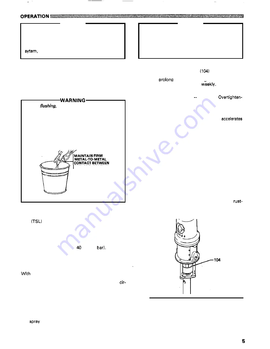
cluding fluid injection, splashing in the eyes or on
the skin, or injury from moving parts, always
follow the Pressure Relief Procedure on page
when checking or servicing any part of the spray
when installing, cleaning or changing
spray tips, and whenever you stop spraying.
Flush the Pump Before Using
Pumps are tested with light weight motor oil which is
left
in to protect the pump parts.
To
prevent contamina-
tion of the fluid, flush the pump with a compatible
sol-
vent before using
it.
If the pump is being used to supply
a
circulating system, allow the solvent to circulate until
the pump is thoroughly flushed.
flushing pails are properly grounded. Refer to
Before
be sure the entire system end
Grounding on page
Follow the Pressure
Relief Procedure on page
2,
and
remove the
spray tip from the gun.
Always use the lowest
to-metal contact between the gun and the pail
possible fluid pressure, and maintain firm metal-
during flushing to reduce the risk of fluid injection
injury, static sparking and splashing.
GUN
AND CONTAINER
Starting and Adjusting the Pump
quid
before operating the pump to help prolong
Fill the wet-cup one-half full with Graco Throat Seal Li-
the packing life.
See
2. See
ACCESSORIES on page
to order TSL.
Trigger the spray gun into a grounded metal waste con-
tainer, -then slowly turn on the air regulator until the
pump begins to cycle, about psi
(2.8
Allow the
pump to cycle slowly until
all
air
is
purged from the fluid
the gun is flowing in a steady stream. Release the gun
lines. The lines are purged when the fluid emitted from
trigger; the pump will stall against pressure.
the pump and lines primed, and with adequate air
stop as the spray gun is triggered and released. In
a
pressure and volume supplied, the pump will
start
and
culating system,
it
will run continuously and speed up or
slow down as supply demands until the air supply is
shut
off.
pressure. Always use the lowest air pressure needed to
Use
the air regulator to control pump speed and fluid
produce the results you want. Higher pressures waste
fluid and cause premature wear of the pump packings
and
tip.
WARNING
To reduce the risk of serious bodily injury,
in-
cluding fluid injection, splashing in the eyes or on
the skin, and property damage, never exceed the
maximum air and fluid working pressure of the
lowest rated component in your system.
See
EQUIPMENT MISUSE HAZARD, System
Pressure, on page
Care
of
the Pump
Keep the wet-cuplpacking nut
one-half full of
tect and
throat oackina life. Check the
Graco Throat Seal Liquid, see Accessories, to help pro-
tightness of the- packing nut
See Fig
ALWAYS
follow the Pressure Relief Procedure, on
page
2,
before adjusting the packing nut. Then tighten
it
just enough to stop leakage no tighter.
ing will compress and damage the packings.
pumped. A dry pump will quickly accelerate to a high
Never allow the pump to run dry of the fluid being
speed, and may damage itself. If your pump
quickly or is running too fast, stop
it
immediately and
check the fluid supply. If the supply container is empty
and air has been pumped into the lines, refill the supply
container and prime the pump, being sure to purge
ell
air
from the fluid system, or flush the pump as described in
Shutdown, below. A pump runaway valve automatical-
ly alerts you to this problem.
See
INSTALLATION.
Shutdown
Always follow the Pressure Relief Procedure on page
2,
whenever you shut off the pump.
Always stop the pump
at the bottom of its stroke to
keep fluid from drying on the exposed displacement rod
and damaging the throat packings.
Alwaysflush the pump with
a
compatible solvent before
fluid can dry in the pump and hoses. After flushing,
even for overnight storage, fill the pump with a
inhibiting solvent, such as mineral spirits, to prevent
corrosion, then relieve pressure.
Fig
2
307-619
Summary of Contents for HYDRA-SPRAY 218-058 A
Page 15: ...307 619 15...


