background image

Service

Repair Kits

A pump seal kit is available for each pump size. Throat

packing kits are also available, one for UHMWPE/

leather pumps and one for PTFE pumps. The piston

seals may also be converted to PTFE. Refer to page

36 for ordering.

Parts supplied in the pump seal kit are marked with

one asterisk in the text and drawings, for example (2*).

Parts supplied in the throat packing kit are marked with

a symbol, for example (19

). For the best results, use

all the parts in the kit.

Disassembling the Displacement Pump

1. Remove the pump from the motor as explained on

page 18.

2. Secure the displacement pump intake housing (10)

in a vise.

3. Refer to Fig. 9. Remove the four capscrews (9)

and washers (8) from around the pump outlet

housing (22).

4. Remove the outlet housing (22), balls (23), seats

(24) and gaskets (7).

5. Remove the three tie bolts (13) and lockwashers

(14). Lift off the upper pump housing (1), along

with the fluid tubes (3), cylinder (4), and piston

assembly (16).

6. Remove the packing nut (21), glands (19, 26) and

packings (20, 25) from the upper housing (1).

NOTE: 

Model 237–220 and 237–221 displacement

pumps use 5 PTFE v-packings in the throat, instead of

3 UHMWPE (20) and 2 leather (25).

7. Remove the tubes (3) and cylinder (4) from the

housing.

8. Remove the intake housing (10) from the vise.

9. Remove the four capscrews (9) and washers (8)

from the intake housing (10). Use a flatblade

screwdriver inserted between the lower pump

housing (11) and the intake housing (10) to sepa-

rate the parts.

10. Remove the balls (5), seats (6 and 32) and gas-

kets (7).

NOTE: 

One of the seats (32) has a vent hole. Take

note of the side of the pump in which this seat is used

(the left side when viewed as shown in Fig. 9).

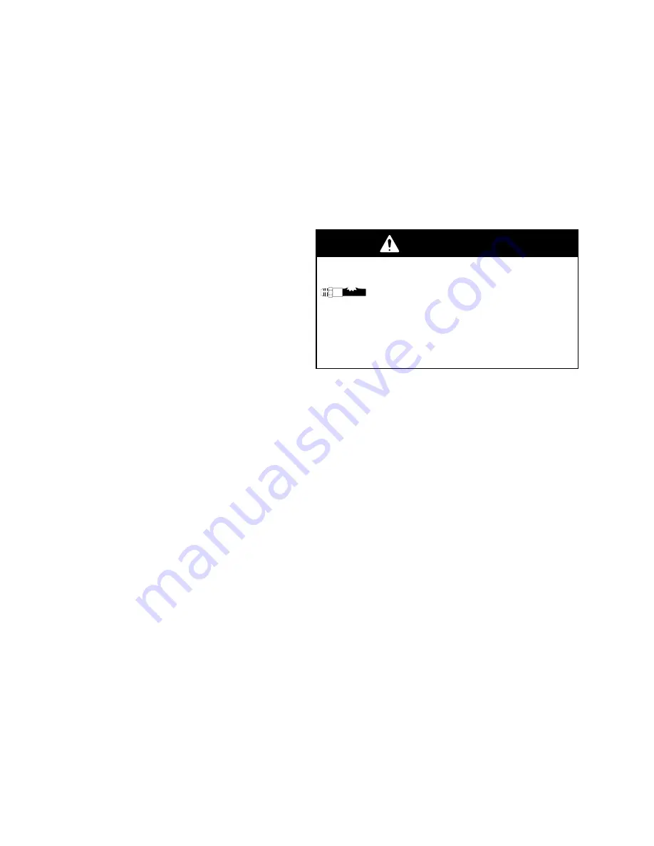
WARNING

COMPONENT RUPTURE HAZARD

The vented ball seat (32) must be in-

stalled at the fluid inlet. This valve

relieves pressure trapped in the pump

cylinder when the pump is shut off, and reduces

the risk of pump overpressurization. The seat

cannot relieve pressure if installed in any other

position.

NOTE: 

Inspect the parts of the piston assembly (items

12, 15 and 16) in place before disassembling the

piston. The piston seal (15) is included in the Seal

Repair Kit. If it or any other parts of the piston show

wear or damage, proceed to step 11. If no damage is

apparent, it is not necessary to disassemble the piston.

11. Place the flats of the piston nut (12) in a vise.

Unscrew the rod (17) from the nut. Disassemble

the two halves of the piston (16) and remove the

seal (15).

Cleaning and Inspecting Parts

Clean all parts in a compatible solvent. Inspect all

parts for wear or damage. If you are using a repair kit,

use all the new parts in the kit, discarding the old ones

they replace. Replace any other parts as needed.

Worn or damaged parts may cause the pump to per-

form poorly or cause premature wear of the new seals

and packings.

Summary of Contents for HIGH-FLO 220-568

Page 1: ...VOLUME HIGH FLO Pumps NOTE Stainless steel pumps are severe duty and electropolished for use with water base coatings Refer to page 2 for the Table of Contents For Pump Model Nos Ratios and Working P...

Page 2: ...15 Troubleshooting 17 Service 18 Parts President Pumps 24 Quiet Senator Pumps 28 Quiet Bulldog Pumps 29 Viscount Pumps 31 Carbon Steel Displacement Pumps 32 Electropolished Stainless Steel Displaceme...

Page 3: ...Viscount I 31 10 3 103 1500 2 1 21 300 236 712 A Viscount I 31 10 3 103 1500 1 5 15 225 SEVERE DUTY ELECTROPOLISHED STAINLESS STEEL MODELS Maximum Air or Hydraulic Working Pressure Maximum Fluid Work...

Page 4: ...maximum working pressure stated on the equipment or in the Technical Data for your equipment Do not exceed the maximum working pressure of the lowest rated component in your system Use fluids and sol...

Page 5: ...ebris including solvent rags and gasoline Electrically disconnect all equipment in the spray dispense area Extinguish all open flames or pilot lights in the spray dispense area Do not smoke in the spr...

Page 6: ...6 307 809 Notes...

Page 7: ...ump ground the system as explained below Also read the section FIRE AND EXPLOSION HAZARD on page 5 1 Pump use the ground wire and clamp See Fig 1 Loosen the grounding lug locknut W and washer X Insert...

Page 8: ...The air regulator L controls pump speed 4 The pump runaway valve P shuts off the air to the pump if the pump speed exceeds your pre ad justed setting Running a pump too fast can dam age it 5 The air...

Page 9: ...d Line 25 mm 1 in minimum diameter F Surge Tank Stand G Surge Tank H Ground Wire required see page 7 for installation J Air Supply Line K Airline Filter L Air Regulator and Gauge M Bleed Type Master A...

Page 10: ...line K controls the hydraulic pressure to the motor Hydraulic Return from Motor NOTE The motor s hydraulic outlet is 7 8 in 37 flare Use a minimum 16 mm 5 8 in ID hydraulic return line K 1 The shutoff...

Page 11: ...H Ground Wire required see page 7 for installation J 10 Micron Return Filter K Hydraulic Return Line 16 mm 5 8 in minimum diameter L Hydraulic Supply Line 13 mm 1 2 in minimum diameter M Drain Line P...

Page 12: ...heck or service any of the system equipment or install or clean the spray nozzle 1 Shut off the power to the pump 2 In an air powered system close the air regulator and close the bleed type master air...

Page 13: ...ording to the instructions supplied with it 9 Adjust the lubricator N according to the instruc tions supplied with it NOTE In a circulating system the pump operates continuously until the power supply...

Page 14: ...e 11 Open the flow control valve S slowly until the cycle rate and fluid pressure return to the desired level This method of setting the hydraulic controls ensures proper pump operation and prevents p...

Page 15: ...e repairing the pump if possible 3 Flush before the fluid you are pumping can dry out settle or set up in the pump and hoses Packing Nut Tightness The packing nut 21 should be tight enough to stop lea...

Page 16: ...mage the pump Stop the Pump at the Bottom of Its Stroke WARNING To reduce the risk of serious injury whenever you are instructed to relieve pressure always follow the Pressure Relief Procedure on page...

Page 17: ...ates erratically Exhausted fluid supply Refill and reprime pump Held open or worn check valves Check and repair Worn piston packing 15 Replace See page 20 Excessive hydraulic fluid supply pres sure to...

Page 18: ...as shown in Fig 6 Position the displacement pump D on the tie rods C Lubri cate the threads of the tie rods Screw the locknuts B onto the tie rods loosely Screw the coupling nut K onto the piston rod...

Page 19: ...55 ft lb 1 3 2 01927 L G K H E C B D Model 236 601 Viscount I Pump Shown 01928 Fig 7 1 3 2 Lubricate threads Torque to 102 109 N m 75 80 ft lb Torque to 68 75 N m 50 55 ft lb E L C B G K H D 1 3 2 019...

Page 20: ...9 and washers 8 from the intake housing 10 Use a flatblade screwdriver inserted between the lower pump housing 11 and the intake housing 10 to sepa rate the parts 10 Remove the balls 5 seats 6 and 32...

Page 21: ...own 16 15 16 12 14 13 9 8 10 7 5 11 17 2 3 2 18 1 19 20 26 21 31 22 9 8 23 24 7 Lips of v packings must face down 25 INLET OUTLET 01930 20 20 25 18 4 17 Ref 5 6 7 32 Vented seat Non vented seat 1 2 3...

Page 22: ...ate the throat packings and glands Install them one at a time in the throat of the upper pump housing 1 Make sure the lips of the v packings face down into the housing and use a finger to seat the par...

Page 23: ...8 81 N m 50 60 ft lb Torque to 34 40 N m 25 30 ft lb Tighten uniformly Apply sealant to threads Left side 01931 5 6 7 8 17 13 4 12 6 7 5 32 9 24 9 22 9 Outside 9 1 2 3 4 5 5 5 6 7 8 10 11 12 Chamfered...

Page 24: ...86 071 PLATE adapter 1 115 183 351 LABEL ID not shown 1 SEVERE DUTY ELECTROPOLISHED STAINLESS STEEL PUMPS Model 220 562 Series A 1 5 1 Ratio Model 220 563 Series A 2 1 Ratio Model 220 564 Series A 3 1...

Page 25: ...l 220 561 Series A 3 1 Ratio Model 237 223 Series A 3 1 Ratio SEVERE DUTY ELECTROPOLISHED STAINLESS STEEL PUMPS Model 220 562 Series A 1 5 1 Ratio Model 220 563 Series A 2 1 Ratio Model 220 564 Series...

Page 26: ...rn sst 1 npt m 1 206b 178 941 NUT hex 1 5 8 18 unef 2b 1 206c 185 394 ADAPTER return 1 5 8 18 unef 2a m x 1 npt f x 1 npt f 1 206d 108 761 ELBOW street 1 npt m x f 1 207 185 466 NIPPLE half 1 1 2 npt...

Page 27: ...gitator Includes items 201 208 Ref No 206 includes items 206a 206d Ref No 205 includes items 205a 205c Connect air hose 205b not shown to air regulator inlet fitting B 201 202 205a B 203 A 207 206a 20...

Page 28: ...page 32 1 108 108 527 NUT lock hex 9 16 12 unc 3 113 181 096 LABEL ID not shown 1 SEVERE DUTY ELECTROPOLISHED STAINLESS STEEL PUMPS Model 220 568 Series A 3 5 1 Ratio Model 220 569 Series A 5 1 Ratio...

Page 29: ...not shown 1 SEVERE DUTY ELECTROPOLISHED STAINLESS STEEL PUMPS Model 220 578 Series A 4 1 Ratio Model 239 815 Series A 4 1 Ratio Ref Part No No Description Qty 101 215 255 MOTOR Quiet Bulldog See 307...

Page 30: ...Notes...

Page 31: ...in 16 mm 4 113 100 214 LOCKWASHER 0 318 4 114 189 206 PLATE adapter 1 SEVERE DUTY ELECTROPOLISHED STAINLESS STEEL PUMPS Model 236 602 Series A Model 236 606 Series A Model 236 713 Series A Ref Part N...

Page 32: ...1 33Y 183 478 PLATE warning 1 34 100 508 SCREW drive type U 3 16 long 2 These parts are included in the Seal Repair Kit which may be purchased separately Refer to the Parts Matrix to determine the cor...

Page 33: ...D For Pump Models 220 561 220 566 and 236 601 Model 237 221 Series A For Pump Model 237 223 NOTE See Service Section for important assembly procedures torque notes and sealants 01936 16 15 16 12 14 13...

Page 34: ...NG throat See Matrix 26 187 117 GLAND female sst 1 31 110 208 PLUG pipe headless 1 8 npt sst 2 32 220 996 SEAT valve vented 1 33Y 183 478 PLATE warning 1 34 103 972 SCREW drive type U 3 16 long 2 Thes...

Page 35: ...Pump Models 220 564 220 569 and 236 602 Model 239 820 Series A for Pump Model 239 819 Model 237 220 Series A for Pump Model 237 222 NOTE See Service Section for important assembly procedures torque no...

Page 36: ...Description Qty 2 108 526 Packing 6 7 181 877 Gasket 4 15 187 761 Packing PTFE 1 18 181 875 Gasket 2 Pump PTFE Seal Conversion Kit 224 935 For Pump Models 220 565 220 568 220 560 220 563 236 605 and...

Page 37: ...27 kg 59 lb Senator CST 1260 mm 49 60 in 712 mm 28 04 in 36 kg 80 lb Senator SST 1260 mm 49 60 in 712 mm 28 04 in 33 kg 73 lb Bulldog CST 1258 mm 49 53 in 712 mm 28 04 in 42 kg 92 lb Bulldog SST 1258...

Page 38: ...bar 120 psi Maximum Working Pressure Shuts off air supply to the pump if the pump accelerates beyond the pre adjusted setting due to an empty supply container interrupted fluid supply to the pump or...

Page 39: ...draulic Shutoff Valve 102 644 For hydraulic supply or return line 3 4 npt f Hydraulic Supply and Return Hose 10 5 MPa 105 bar 1500 psi Maximum Working Pressure 5 8 in ID coupled 3 4 npt x 7 8 14 90 sw...

Page 40: ...Pa 4 9 bar 70 psi air pressure C 0 28 MPa 2 8 bar 40 psi air pressure PUMP DELIVERY Test Fluid No 10 Motor Oil 2 1 Ratio President Pumps Models 220 560 and 220 563 Maximum Working Pressure 2 5 MPa 25...

Page 41: ...MP DELIVERY Test Fluid No 10 Motor Oil PUMP OUTLET PRESSURE AIR CONSUMPTION 12 25 37 50 62 74 CPM 87 8 15 23 30 38 46 54 GPM l min 30 20 10 0 1 96 0 84 0 28 CFM m3 min 70 0 56 40 1 12 50 1 40 60 1 68...

Page 42: ...air consumption A 0 7 MPa 7 bar 100 psi air pressure B 0 49 MPa 4 9 bar 70 psi air pressure C 0 28 MPa 2 8 bar 40 psi air pressure 2 5 1 Ratio Quiet Senator Pumps Models 220 567 and 220 570 Maximum Wo...

Page 43: ...M m3 min PUMP OUTLET PRESSURE AIR CONSUMPTION A B C A B C PUMP DELIVERY Test Fluid No 10 Motor Oil 1 4 14 0 7 7 PSI 1 05 10 5 0 35 3 5 1 7 17 2 45 24 5 MPa BAR 2 1 21 2 8 28 To find Outlet Pressure MP...

Page 44: ...44 307 809 Notes...

Page 45: ...56 CFM m3 min PUMP OUTLET PRESSURE AIR CONSUMPTION A B C A B C PUMP DELIVERY Test Fluid No 10 Motor Oil 1 4 14 0 7 7 PSI 1 05 10 5 0 35 3 5 1 7 17 2 45 24 5 MPa BAR 2 1 21 2 8 28 To find Outlet Press...

Page 46: ...MPa 34 bar 500 psi hydraulic oil pressure 1 4 14 0 7 7 PSI 1 05 10 5 0 35 3 5 1 7 17 2 45 24 5 MPa BAR 2 1 21 2 8 28 3 4 34 3 15 31 5 Viscount I Pumps Models 236 605 and 236 606 Maximum Working Press...

Page 47: ...ific delivery liter min or gpm and operating hydraulic pressure MPa bar psi 1 Locate desired delivery along bottom of chart 2 Read vertical line up to intersection with selected fluid outlet pressure...

Page 48: ...ot limited to incidental or consequential damages for lost profits lost sales injury to person or property or any other incidental or consequential loss shall be available Any action for breach of war...

Reviews: