background image

Instructions – Parts List

GRACO INC.ąP.O. BOX 1441ąMINNEAPOLIS, MNą55440-1441

Copyright 1992, Graco Inc. is registered to I.S. EN ISO 9001

308219G

WARNING

FIRE, EXPLOSION, AND ELECTRIC
SHOCK HAZARD

The operating and safety features of this heater are
designed for use 

only

 with the Graco Foam-Cat

r

Heated Hoses: Models 218613 and 218614. To
reduce the risk of serious injury, never connect
other hoses to this heater.

CSA certified for use with 218613,
Series B, and 218614, Series B,
Heated Hoses.

Read warnings and instructions.

See page 2 for Table of Contents.
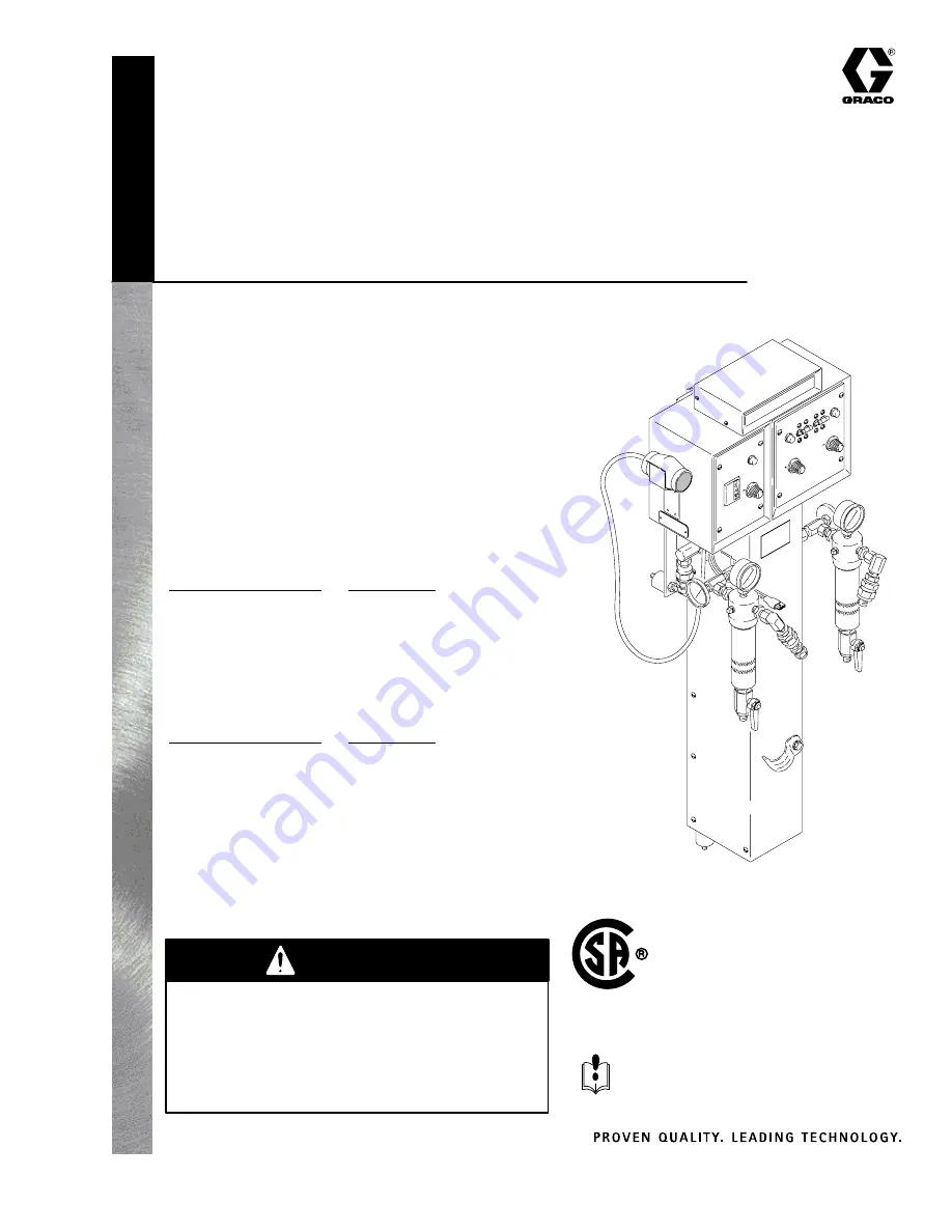
FOAM–CAT

R

 HEATER

For use ONLY with two component urethane fluids that are unfilled
and non–flammable.

3000 psi (21 MPa, 210 bar) Maximum Working Pressure
Temp. Class T2C (230

_

 C) Maximum Fault Temperature

Nominal Operating Temperature: 95–158

_

 F (35–70

_

 C)

Ambient Temperature Range: 40–104

_

 F (5–40

_

 C)

This heater includes a heating element and an independent
temperature for each of two fluids, Isocyanate and Resin,
and an independent temperature control for the Foam–Cat

r

Heated Hose.

Foam-Cat

r

 200

 15 

lb/min

Model 235259

With Heated Hose Control

Series B

8880 Watt

Model 235839

Without Heated Hose Control

Series B

5100 Watt

Foam-Cat

r

 400

 30 

lb/min

Model 235260

With Heated Hose Control

Series B

13,980 Watt

Model 235840

Without Heated Hose Control

Series B

10,200 Watt

U.S. Patent No. 4,501,952; 4,725,713
U.K. Patent No. 2,138,601
Patented Bréveté 1986 Canada

01292

Summary of Contents for FOAM-CAT 200 Series

Page 1: ...ane fluids that are unfilled and non flammable 3000 psi 21 MPa 210 bar Maximum Working Pressure Temp Class T2C 230_ C Maximum Fault Temperature Nominal Operating Temperature 95 158_ F 35 70_ C Ambient...

Page 2: ...re Compensator 22 Heater Element 22 Hose Sensor Simulator 22 Hose Control Circuit Board 23 Triac 24 Service 25 Triac 25 Hi Limit Thermostat 26 Heater Sensor Probe 27 Heater Element 28 Circuit Board 30...

Page 3: ...hose when it is coiled D Do not use the hoses to pull the equipment D Use only Graco Foam Catr Heated Hoses Models 218613 and 218614 D Use fluids and solvents that are compatible with the equipment w...

Page 4: ...nozzle D Do not stop or deflect leaks with your hand body glove or rag D Do not blow back fluid this is not an air spray system D Always have the trigger guard on the spray gun when spraying D Be sure...

Page 5: ...nnect all equipment in the spray area D Before operating this equipment extinguish all open flames or pilot lights in the spray area D Do not smoke in the spray area D Do not turn on or off any light...

Page 6: ...id filter drain valves have a container ready to catch the draining fluid 11 If you suspect that the spray tip nozzle or hose is completely clogged or that pressure has not been fully relieved after f...

Page 7: ...the correct routing of all air and fluid hoses KEY A Fluid Hose Displacement Pump to Heater B Heated Hose C Main Air Supply Hose D Air Manifold E Optional ATC Sensor F Air Hose Heated Hose 107 Inlet...

Page 8: ...e heated hose has an independent Temperature Set dial K a main power circuit breaker 210 and 319 and an indicator light 214 and 314 on the control panel The independent circuit breakers turn on or off...

Page 9: ...bient Temperature Compensator ATC Most fluid heaters produce or output just the amount of heat selected on its TEMP SET dial regardless of ambient temperature changes during the day So in order to mai...

Page 10: ...r WARNING ELECTRIC SHOCK HAZARD To reduce the risk of electric shock do not expose the heater to rain If you have purchased the heater module separately bolt it securely to the Graco Pump Stand part n...

Page 11: ...to protect it during shutdown 4 Some material suppliers provide maintenance services which include flushing and storage 5 Never flush the hoses It is very difficult to remove all moisture from hoses...

Page 12: ...odel 235260 3 phase 240 VAC Model 235260 1 phase 240 VAC 28 Amps 28 Amps 28 Amps 11 Amps 11 Amps 11 Amps 11 Amps 16 Amps 16 Amps L1 L2 L3 RES HTR 2 6 Kw ISO HTR 2 6 Kw HOSE 3 8 Kw max TB1 TB2 TB3 TB4...

Page 13: ...tive leakage current to ground In a mobile installation be sure the truck or trailer is grounded to a true earth ground 2 Pump connect a ground wire and clamp to a true earth ground as shown in your s...

Page 14: ...age 7 to identify the parts mentioned in this section except where noted other wise 1 Be sure the heater has been flushed 2 Close the feed pump air inlet valves 3 Put a waste container under each heat...

Page 15: ...eater See Fig 7 2 Connect the fluid dispense hoses of the heated hose assembly to the fluid outlet union 113 of each fluid filter 3 Connect a main air supply hose C to the manifold D on the side of th...

Page 16: ...urning on the circuit breakers With fluid flowing only check the heater thermometers 204 regularly and manually adjust the fluid temperature as needed See Fig 8 6 The heated hose control lamp should s...

Page 17: ...81 Check triac wiring See Fig 13 page 25 Faulty circuit board 223 or 306 Replace See page 30 Faulty Hose Sensor Simulator 304 Be sure simulator is firmly plugged into circuit board Check simulator res...

Page 18: ...page 20 Faulty Triac Check triac wiring See Fig 12 page 24 Check resistance See page 24 The ATC if used is not plugged in Be sure ATC connector if used is properly plugged into circuit board Check re...

Page 19: ...h pressure side is too thick Increase heater temperature on high pressure side to reduce viscosity which should level the pressure OR lower the temperature on the low pressure side WARNING As this pro...

Page 20: ...each wire on the terminal block push the tool away from the wire and pull out the wire See Fig 9 5 To reconnect the wires push the tool into the slot slide in the wire and release the tool Fig 9 01698...

Page 21: ...ONNECTOR N T C TEMP DIAL A B J2 J1 G MT2 MT1 M M WHT WHT BLK BLK 4 3 2 1 LAMP BOARD A B C LIMIT THERMOSTAT ELEMENTS CIRCUIT BREAKER 1 2 3 4 5 6 A A B B CAL POWER IN TERMINAL BLOCK TB OPTIONAL ATC P1 O...

Page 22: ...l panel 216 See Fig 13 page 25 3 Use the procedure in Setup to disconnect the wires in step 4 4 Check the resistance across wires 7 and 8 and 9 and 10 on the RES board Check the resistance across wire...

Page 23: ...TIONAL ATC P1 OPTIONAL P1 STANDARD P2 CONNECTOR TEMP DIAL A B J2 J1 G MT2 MT1 M M WHT WHT BLK BLK 4 3 2 1 LAMP BOARD A B C 1 2 3 4 5 6 A A B B CAL POWER IN TERMINAL BLOCK TB A B GFI HOSE CONNECTOR TRI...

Page 24: ...Fig 12 Replace the triac if any one of the readings is incorrect NOTE When using a digital V O M with automatic range for example a Model 77 Fluke infinity 10 megohms or greater 4 To replace the tria...

Page 25: ...ical power to the heater before removing any heater panels Replacing the Triac 1 Relieve the pressure and shut off the main power to the heater 2 The triac leads should be disconnected if you performe...

Page 26: ...nnect the wires to the thermostat 252 See Fig 14 4 Remove the screws lockwashers and the thermo stat 5 Apply conductive paste order Graco P N 110009 to the bottom flange of the new thermostat 6 Instal...

Page 27: ...47 from the manifold 253 See Fig 15 6 Push the probe 247d through the adapter 247c Feed the probe wires through the seal 247b and packing nut 247a Push the seal into the adapter 247c and then apply PT...

Page 28: ...ect the heating element wire from the thermostats 5 Pull the disconnected wires out the bottom Be careful not to pull the connectors off the wires 6 Remove all four nuts 102 and lockwashers 103 from t...

Page 29: ...acket over the threaded shafts of the cylindrical mounts 104 and 105 Install the lockwashers 103 and nuts 102 18 Connect the heating element wire to the Hi Limit Thermostat 19 Reinstall the heater ele...

Page 30: ...NOTE Use replacement part 235255 Disassembly 1 Relieve the pressure and shut off the main power to the heater 2 Remove the control panel cover 216 or 317 3 Unplug the wires leading to the TEMP SET di...

Page 31: ...nd 21 7 Plug in the wires leading to the TEMP SET dial 213 or 315 See Fig 20 and 21 8 Plug the sensor probe connector P2 into the circuit board at position J2 See Fig 20 and 21 9 Reinstall the control...

Page 32: ...read very low during no flow conditions This is due to the influence of the metal surrounding the gauge which is exposed to the air 6 If the temperature is not within range a Turn the circuit breakers...

Page 33: ...33 308219 Notes...

Page 34: ...circuit breaker and set the temperature dial to CAL Allow the heater to warm up 3 If adjusted properly the light on the hose control panel should be ON about 80 of the time and OFF about 20 of the tim...

Page 35: ...309 4 Fig 23 OPTIONAL ATC P1 OPTIONAL P2 CONNECTOR TEMP DIAL A B J2 J1 G MT2 MT1 M M WHT WHT BLK BLK 3 2 1 LAMP BOARD A B C 1 2 3 4 5 6 A A B B CAL POWER IN TERMINAL BLOCK TB A B GFI HOSE CONNECTOR TR...

Page 36: ...4 107 206831 CHECK VALVE 3 8 npsm swivel x 3 8 npt m 4 108 168696 NIPPLE adapter 3 8 npsm x 3 8 npt f 2 110 215623 BALL VALVE 3 8 npt mbe 2 111 178747 LEVER valve 2 112 218029 FLUID FILTER see 307273...

Page 37: ...9 235253 CONTROL BOX heated hose 1 310 188053 LABEL instruction 1 311 065278 COPPER WIRE 14 AWG 24 in 312 105362 CLAMP cable 2 313 217384 CABLE power 1 314 104340 LAMP indicating 1 315 103083 KNOB sel...

Page 38: ...0 24 x 3 8 18 216 188056 COVER heater control panel 1 218 103854 SCREW bdgh 6 32 x 1 4 8 221 102556 RIVET blind 2 222 180254 PLATE serial 240 V 1 223 235255 CIRCUIT BOARD includes item 223a 2 223a 106...

Page 39: ...035 MOLDING 14 in 240 217237 PANEL rear enclosure 1 241 217239 BRACKET manifold 1 242 188058 MANIFOLD probe thermostat 4 243 188064 U TUBE fluid 2 244 188054 NIPPLE 2 8 2 245 217236 COIL heater elemen...

Page 40: ...201 100642 CAPSCREW hex hd 1 4 20 x 1 1 4 4 202 100016 LOCKWASHER 4 204 102124 THERMOMETER dial 50 250_ F 10 120_ C range 2 264 178825 UNION 90_ 1 4 18 F x 3 8 18 m x 3 8 F swivel 2 Ref No Part No Des...

Page 41: ...WITCH 24 TB1 240V SWITCH RESIN HEATER ISO HEATER Model 235840 OPTIONAL ATC P1 OPTIONAL ATC OPTIONAL ATC P1 OPTIONAL ATC 01300 1 2 A A B B 11 12 M M 4 3 2 1 7 8 J2 J1 22 TEMP SET FRONT HTR Q1 TRIAC T1...

Page 42: ...2 mm Overall width D 8 1 205 mm E 8 1 205 mm F 5 1 129 mm G 2 0 51 mm H 8 6 217 mm I 39 6 1005 mm J 8 1 205 mm K 6 1 154 mm L 29 0 736 5 mm M 5 2 132 mm N 8 5 216 mm Fittings O 3 8 npt m ISO P 3 8 npt...

Page 43: ...Approximate Temperature Rise Capabilities Model 235839 70_ to 120_F at 1 5 gpm of oil 31_ to 49_C at 5 7 l min of oil Model 235840 70_ to 120_F at 3 0 gpm of oil 31_ to 49_C at 11 4 l min of oil Elect...

Page 44: ...l be as set forth above The buyer agrees that no other remedy including but not limited to incidental or consequential damages for lost profits lost sales injury to person or property or any other inc...

Reviews: