background image

CONTINUITY TESTING

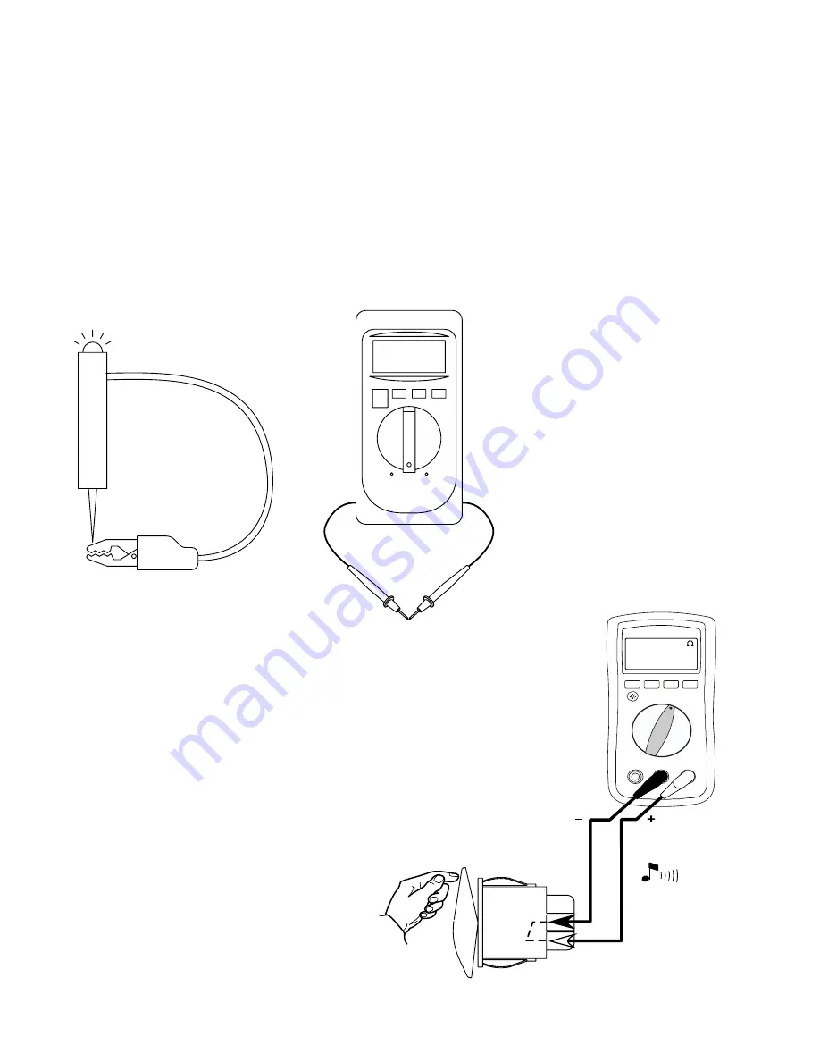
Checking “continuity” is one of the most common tests in electrical troubleshooting. Continuity is the ability of a wire or electrical component to 

conduct current. When you use a continuity tester, you connect a circuit (the continuity tester) that you know works, to a wire or a component that 

may or may not work. The continuity tester will tell you if the wire or component is capable of conducting current.

Continuity testers are available at almost any hardware store.

A volt-ohmmeter or VOM can also be used to check continuity. This meter can be purchased at most electrical or electronic supply stores.

To test a component for continuity:

1  Check the tester by connecting the leads.

* If using a test light the light should turn on.

* If using a digital volt-ohmmeter, the screen should show 00 if OL appears the meter needs to be repaired.

SWITCH TESTING-ROCKER

Common test procedure for a SPST Switch:

0.000

5

Summary of Contents for Finishpro 390

Page 1: ...be used by a qualified Service Technician FinishPro 390 395 Airless Air Assisted Sprayer Repair Electrical Manual Black Red Yel Yel 3 00 First choice when quality counts ti9026a FinishPro 395 FinishPr...

Page 2: ...ir Compressor Air Compressor will not start 16 Air Compressor runs but will not build pressure 17 Air Compressor is trying to start humming 10 FinishPro 395 ON OFF Switch Test 18 19 Switch Ladder Diag...

Page 3: ...power source to the load Current is measured in AMPERES AMPS A or I See Figure 1 NOTE Meter is only clamped around one wire VOLTAGE Voltage is the force that causes current to flow in a circuit Volta...

Page 4: ...tion to the flow of current in a circuit Resistance is used to control the amount of voltage and or amperage in a circuit Resistance is measured in OHMS See Figure 3 A common component check would be...

Page 5: ...you if the wire or component is capable of conducting current Continuity testers are available at almost any hardware store A volt ohmmeter or VOM can also be used to check continuity This meter can...

Page 6: ...load voltage A good piece of wire will carry line and load voltage Damaged Fragmented Wire Damaged Fragmented Wire Pinched Wire 120 Vac input static voltage and drops to 76Vac load voltage Other caus...

Page 7: ...VOM leads to several bare metal surfaces on the body of the machine If the light or meter indicates continuity the machine is properly grounded If the light or meter doesn t indicate continuity trace...

Page 8: ...remove the capacitor s If capacitor s are attached to the control board the test can not be perormed 3 SEE ABOVE WARNING Using a screwdriver with insulated handles hold so that the blade contacts the...

Page 9: ...fective If the meter beeps go to the next step 3 Connect test leads as shown in Figure C If the meter beeps the rectifer is defective If the meter does not beep go to the next step 4 Connect test lead...

Page 10: ...ES Check the connector for the white wires If ok repair or replace the power Cord Replace the power switch Switch is good Proceed to the proper Test Section NO See step 3 Do you have over 100 AC volts...

Page 11: ...or Power Cord F1 Control Board Airless OFF Air Assisted Airless Mode Switch Down Air Assisited Mode Switch Up Off Switch Center FinishPro 390 Switch Ladder Diagram White White White White White White...

Page 12: ...res See step 5 Does the motor run See Motor Test YES See step 1 Do you have over 100 AC volts YES See step 3 Is there over 100 DC volts YES YES See ON OFF Switch Test NO Replace Pressure Switch Replac...

Page 13: ...AC Volts 110 120AC V BEEP Checking the motor thermistor switch Unplug the motor wires from control board Carefully insert the meter probes into the 2 yellow wires Meter should read continuity Note mo...

Page 14: ...start the motor If motor does not run follow the steps below Step 1 Step 2 Step 4 Checking the motor wires for a short Put the meter lead on the motor case Move the meter lead to each wire Meter shoul...

Page 15: ...once material comes out the prime drain hose turn the prime spray valve to spray Does fluid continue to flow though the drain hose Check the Inlet and Out valves for a stuck ball See freeing up inlet...

Page 16: ...Cord plugged in Meter on AC Volts Compressor AA Mode Airless Mode Off Step 1 J4 Control Board 110 120AC V J3 Connector Power Plug To NO See step 1 Do you have over 100 AC volts YES Does the airless m...

Page 17: ...he Air Compressor will not start section See Air Compressor will not start section Disconnect the air hose from the air solenoid Turn the compressor on Dose the compressor start Replace the air soleno...

Page 18: ...ts NO YES Replace the power switch See step 5 Do you have Continuity NO Replace the power switch FinishPro 395 ON OFF Switch Test Switch is good Proceed to the proper Test Section YES Airless Motor wi...

Page 19: ...gged from switch Meter should show continuity or Beep FinishPro 395 ON OFF Switch Test Compressor Power Cord AA Mode Airless Mode Off Step 1 Power switch in the Airless Mode Cord plugged in Meter on A...

Page 20: ...ack Black Power Cord Compressor Air Assisted Control Board White Blue Brown Black Black Power Cord Compressor White White White Brown Brown Brown Blue Blue Blue FinishPro 395 Switch Ladder Diagram Air...

Page 21: ...ive thermistor switch YES NO See step 3 Is there continuity through the thermistor wires See step 4 Does the motor run See motor test section See Error Codes YES NO See step 1 Do you have over 100 AC...

Page 22: ...gh Meter on DC volts Motor Step 2 Thermistor Wires to motor BEEP Checking the motor thermistor switch Unplug the J11 2 white wires from control board Meter should read continuity Note motor should be...

Page 23: ...re knob clockwise a turn Try to restart the motor If motor does not run follow the steps below Step 1 Step 2 Step 4 Checking the motor wires for a short Put the meter lead on the motor case Move the m...

Page 24: ...nce material comes out the prime drain hose turn the prime spray valve to spray Does fluid continue to flow though the drain hose Check the Inlet and Outlet valves for a stuck ball See freeing up inle...

Page 25: ...l Cord plugged in Meter on AC Volts 110 120AC V Blk Green Blk Yellow Blue White Blk Brn Grn Yel N L N Compressor Power Cord AA Mode Airless Mode Off Step 2 Power switch in the AA Mode Blk meter led on...

Page 26: ...re Relief Valve Replace the Air Regulator NO YES YES Connect a test air gauge to the air hose connector Start the compressor NO Replace the compressor Is the compressor trying to start Humming NO YES...

Page 27: ...nt on Control is commanding motor to run Blinks 2 x repeatedly High pressure signal from transducer Blinks 3 x repeatedly Transducerfailure or connection error Blinks 4 x repeatedly Excessive Wall vol...

Page 28: ...sprayer ON and control knob to turn clockwise If ok replace pot Replace control board if sprayer still does not run But first verify transducer and connections are ok See next page OR Short center pin...

Page 29: ...etal braid in x 50 ft minimum Smaller hose or metal braid hose may result in high pressure spikes 4 Set sprayer to OFF and disconnect power to sprayer 5 Check transducer connections to control board 1...

Page 30: ...control board socket Check that transducer and control board contacts are clean and secure 4 Reconnect transducer to control board socket Connect power set sprayer ON and control knob to turn clockwis...

Page 31: ...l board status light blinks 4x repeatedly What does this mean Voltage applied to the sprayer is too high Troubleshooting Procedure 1 Make sure the sprayer is plugged into the proper AC power source Le...

Page 32: ...ck for locked or frozen pump or drive train If sprayer does not run go to next step 2 Set sprayer to OFF and disconnect power to sprayer 3 Disconnect motor connector s from control board socket s Chec...

Page 33: ...oard Set sprayer to OFF and disconnect power to sprayer 2 Disconnect motor thermal switch wires from control board Check that all connections at the control board are clean and secure 3 If connections...

Reviews: