background image

Maintenance 

16

311593R

Maintenance

Preventive Maintenance 
Schedule

Establish a preventive maintenance schedule based on 
the equipment’s repair history.

Check Gear Reducer Oil Level

Every day, check the oil level in the sight glass (SG) on 
the gear reducer, with the motor running. Oil level (with 
motor running) should fall between top and bottom of 
the sight glass (SG). Open the fill cap (FC) and fill the 
gear reducer oil reservoir as required with Graco 
288414 Oil (package includes twelve 1 quart bottles). 
Do not overfill. See F

IG

. 8.

Gear Box and Drive Lubrication

Replace the gear box lubricant after a break-in period of 
200,000-300,000 cycles. Order 288414 Replacement 
Oil.

Following the break-in period, replace the gear box 
lubricant once a year.
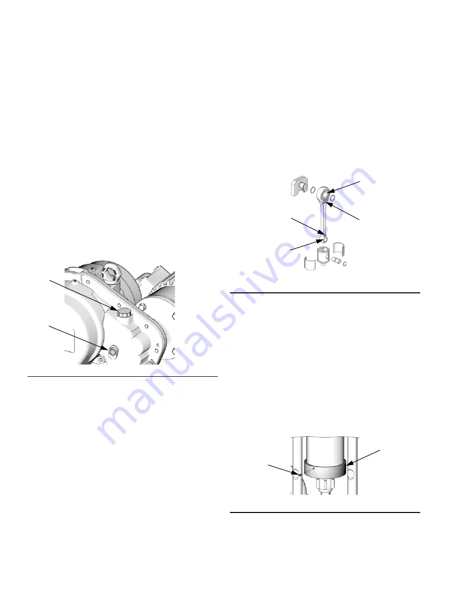
See F

IG

. 9. Every 6 months, lubricate the wrist pin bear-

ing (7a) on the connecting rod with 1 shot (1 cc) of 
107411 Grease or equivalent, using grease zerk (GZ). 
Replace both wrist pin bearings annually. Order Wrist 
Pin Replacement Kit 255216. Lubricate the crank pin 
bearing (X) annually, using grease zerk (GZ).

NOTE: A faint clicking may be heard while the motor is 
running. This is normal and is due to necessary clear-
ances between the coupler (28), motor shaft, and motor 
key. If the intensity increases significantly over time, it 
could indicate the coupler is wearing and should be 
replaced. Do not open the gear reducer. The gear 
reducer is not field serviceable beyond the maintenance 
recommended in this manual

Clean the Slider Cylinder 
Collectors

Every month, check the slider cylinder collectors for dirt 
or debris. Remove the 2-piece shield covering the cou-
pling assembly. Loosen the three set screws (SS) on the 
collector (CL). Lower the collector and wipe the inside 
with a clean, damp cloth. Return the collector to its oper-
ating position. Tighten the screws finger tight. Reinstall 
the shields.

F

IG

. 8. Oil Fill

SG

FC

ti8914a

F

IG

. 9. Lubricate Wrist Pin Bearing Every 6 Months

F

IG

. 10. Slider Cylinder Collector

ti8717a

GZ

7a

GZ

X

ti9539a

CL

SS

Summary of Contents for E-Flo 1500

Page 1: ...h volume paint circulation applications For professional use only See page 3 for model information including maximum working pressure See page 5 for approvals Important Safety Instructions Read all wa...

Page 2: ...ment 13 Operation 14 Pressure Relief Procedure 14 Priming 14 Startup 14 Shutdown 14 Maintenance 16 Preventive Maintenance Schedule 16 Check Gear Reducer Oil Level 16 Gear Box and Drive Lubrication 16...

Page 3: ...Pressure E Flo 2000 460 psi 3 22 MPa 32 2 bar Maximum Working Pressure E Flo 3000 330 psi 2 31 MPa 23 1 bar Maximum Working Pressure E Flo 4000 250 psi 1 75 MPa 17 5 bar Maximum Working Pressure See T...

Page 4: ...Models 4 311593R...

Page 5: ...listings Component Part No Approvals Mechanical Pump Motor ATEX EP1XXX EP3XXX UL CSA EP2XXX EP4XXX IS Sensor Circuit EPX1XX Ex h IIB T3 Gb Ex de IIC T4 CESI 05 ATEX 110X Class I Group D Class II Grou...

Page 6: ...ment until you identify and correct the problem Keep a working fire extinguisher in the work area Static charge may build up on plastic parts during cleaning and could discharge and ignite flammable v...

Page 7: ...equipment can start without warning Before checking moving or servicing equipment follow the Pressure Relief Procedure in this manual Disconnect power or air supply TOXIC FLUID OR FUMES HAZARD Toxic...

Page 8: ...put shaft of the gearbox and the connecting rods experience the effect of the imaginary camshaft by speeding up when the pressure drops pump lower is at a changeover and slowing down when pressure inc...

Page 9: ...ay Solenoid Valve 2 meters provided by Graco P Pump Stand R Fluid Inlet Line S Fluid Outlet Line T Fluid Return Line U Pneumatic Back Pressure Regulator V Air Supply Lines to 3 Way Solenoid Valve W Ai...

Page 10: ...Overview 10 311593R...

Page 11: ...Z to the pump Tighten the screw securely Connect the other end of the ground wire to a true earth ground ti9230a Z GS Variable frequency drive grounded through proper connection to power source Local...

Page 12: ...ontrol box contains five controls See FIG 4 Secure Disable Switch Push in to secure Pull out to disable Start Stop Switch Set to START to start pump Set to STOP to stop pump Alarm Reset Button Press t...

Page 13: ...SL Reservoirs Part No 206995 Throat Seal Liquid TSL carries resi due from the pump rod into the reservoir Fill the TSL reservoirs R with Graco 206994 Throat Seal Liquid TSL See FIG 6 See Changing the...

Page 14: ...3 Set START STOP switch ST to STOP See FIG 4 4 Set the back pressure regulator as desired The system is ready to run Startup 1 Close the main power disconnect 2 Use the VFD to set motor to a low flow...

Page 15: ...20 24 10 300 20 600 30 900 40 1200 50 1500 60 1800 Motor Speed in Hz rpm 0 A B C Equations for each line 2000 cc Flow gpm 1 13 x 1500 cc Flow gpm 0 811 x 1000 cc Flow gpm 0 598 x 750 cc Flow gpm 0 406...

Page 16: ...se zerk GZ Replace both wrist pin bearings annually Order Wrist Pin Replacement Kit 255216 Lubricate the crank pin bearing X annually using grease zerk GZ NOTE A faint clicking may be heard while the...

Page 17: ...rden in the pump wet cup How long TSL lasts depends on which chemicals are used how much is used what pressure and condition of the pump seal and rod A drop in the level of TSL in the reservoir indica...

Page 18: ...s on page 19 Fluid Inlet and Outlet Size 2 in Tri clamp Gear Reducer Oil Capacity 2 quarts 1 9 liters Required Gear Reducer Lubricant ISO VG220 grade oil Graco Part No 288414 Weight with motor and 200...

Page 19: ...95 A B C 400 2 80 28 0 450 3 15 31 5 500 3 50 35 0 D Key A E Flo 1500 B E Flo 2000 C E Flo 3000 D E Flo 4000 Pressure and Flow Capability of E Flo Family with 60 Hz Motor continuous production use Fl...

Page 20: ...n material or workmanship repairs will be made at a reasonable charge which charges may include the costs of parts labor and transportation THIS WARRANTY IS EXCLUSIVE AND IS IN LIEU OF ANY OTHER WARRA...

Reviews: