background image

308996

5

Installation

General Information

NOTE: Reference numbers and letters in parentheses
in the text refer to the callouts in the figures and the
parts drawing.

NOTE: Always use Genuine Graco Parts and Acces-
sories, available from your Graco distributor. If you
supply your own accessories, be sure they are ade-
quately sized and pressure rated for your system.

Prepare the Operator

All persons who operate the equipment must be
trained in the safe, efficient operation of all system
components as well as the proper handling of all fluids.
All operators must thoroughly read all instruction
manuals, tags, and labels before operating the equip-
ment.

Grounding

WARNING

FIRE AND EXPLOSION HAZARD
Before operating the pump, ground the
system as explained below. Also read
the section FIRE AND EXPLOSION
HAZARD
 on page 4.

1.

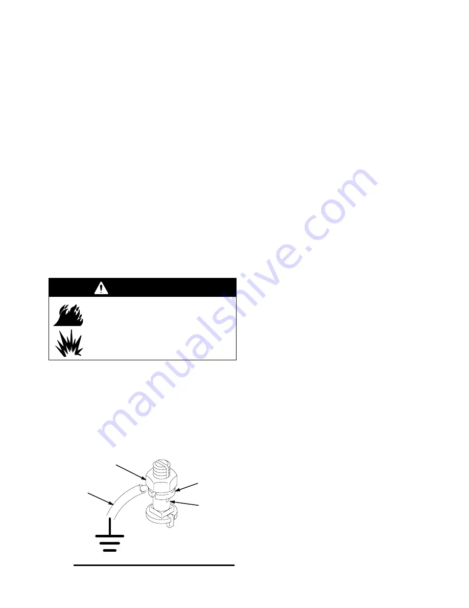
Pump: use a ground wire and clamp. See Fig. 1.
Loosen the grounding lug locknut (W) and washer
(X). Insert one end of a 1.5 mm

@

 (12 ga) minimum

ground wire (Y) into the slot in lug (Z) and tighten
the locknut securely. Connect the other end of the
wire to a true earth ground. Order Part No. 238909
Ground Wire and Clamp.

Fig. 1

W

X

Y

Z

0864

2.

Pump air supply and fluid hoses: Use only electri-
cally conductive hoses with a maximum of 500 feet
(150 m) combined hose length to ensure ground-
ing continuity. Check the electrical resistance of
your air and fluid hoses at least once a week. If the
total resistance to ground exceeds 29 megohms,
replace the hose immediately.

NOTE: Use a meter that is capable of measuring
resistance at this level.

3.

Air compressor: follow manufacturer’s recommen-
dations.

4.

Spray gun: ground through connection to a prop-
erly grounded fluid hose and pump.

5.

Fluid supply container: follow your local code.

6.

Object being sprayed: follow your local code.

7.

Solvent pails used when flushing: follow your local
code. Use only metal pails, which are conductive,
placed on a grounded surface. Do not place the
pail on a nonconductive surface, such as paper or
cardboard, which interrupts the grounding continu-
ity.

8.

To maintain grounding continuity when flushing or
relieving pressure
, hold a metal part of the spray
gun firmly to the side of a grounded metal pail,
then trigger the gun.

System Accessories

Fig. 2 is only a guide for selecting and installing sys-
tem components and accessories. Contact your Graco
distributor for assistance in designing a system to suit
your particular needs.

Air and Fluid Hoses

Ensure that you have an adequate compressed air
supply. Bring a compressed air supply line from the air
compressor to the pump location.

Be sure all air hoses (H and D) and fluid hose (N) are
properly sized and pressure-rated for your system.
Use only electrically conductive hoses. Fluid hoses
must have spring guards on both ends.

The air hose (H) should have a 3/8 npt (m) thread. A
quick disconnect coupling is recommended.

Mounting Accessories

Mount the pump (A) to suit the type of installation
planned. Fig. 2 illustrates a wall mount system. Pump
dimensions and the mounting hole layout are shown
on page 25.

Summary of Contents for 308996J

Page 1: ...r Maximum Air Input Pressure Part No 241595 Pump Series B 20 1 Ratio with Falcon II Air Motor 2200 psi 15 MPa 152 bar Maximum Fluid Working Pressure 100 psi 0 7 MPa 7 bar Maximum Air Input Pressure Ch...

Page 2: ...ll instruction manuals tags and labels before operating the equipment D Use the equipment only for its intended purpose If you are not sure contact your Graco distributor D Do not alter or modify this...

Page 3: ...safety operates before spraying D Do not allow children to use this equipment D Lock the gun trigger safety when you stop spraying D Follow the Pressure Relief Procedure on page 8 whenever you are in...

Page 4: ...debris including solvent rags and gasoline D Electrically disconnect all equipment in the spray area D Extinguish all open flames or pilot lights in the spray area D Do not smoke in the spray area D...

Page 5: ...o ground exceeds 29 megohms replace the hose immediately NOTE Use a meter that is capable of measuring resistance at this level 3 Air compressor follow manufacturer s recommen dations 4 Spray gun grou...

Page 6: ...ontrols pump speed and out let pressure by adjusting the air pressure to the pump Locate the regulator close to the pump but downstream from the bleed type master air valve D An air regulator Z adjust...

Page 7: ...L Pump Outlet M Wet Cup N Electrically Conductive Fluid Supply Hose R Gun Swivel S Air Assisted Spray Gun T Suction Hose U Strainer Y Ground Wire and Clamp required see page 5 for installation instruc...

Page 8: ...vice any of the system equipment D or install or clean the spray tips 1 Lock the gun trigger safety 2 Shut off the air supply to the pump 3 Close the bleed type master air valve E required in your sys...

Page 9: ...y and air has been pumped into the lines refill the con tainer and prime the pump and the lines or flush and leave it filled with a compatible solvent Eliminate all air from the fluid system 11 With p...

Page 10: ...r fluids D Before fluid drys or settles out in a dormant pump check the pot life of catalyzed fluids D Before storing the pump Flush with a fluid that is compatible with the fluid you are pumping and...

Page 11: ...ed valves Clear the line increase the air supply Check that the valves are open Obstructed fluid hose or gun the fluid hose ID is too small Open clear use a hose with a larger ID Worn u cup seals in t...

Page 12: ...pliers remove cotter pin 107 from clevis pin 106 Remove clevis pin from displacement rod 1 6 Hold tie rod flats with wrench to keep rods from turning Unscrew nuts 108 from tie rods 105 Carefully remov...

Page 13: ...308996 13 Service 9094B 1 Fig 3 101 109 108 107 105 106 2 1 V U W Torque to 120 130 in lb 10 11 NSm 1 1 Model 241594 Shown...

Page 14: ...of outlet housing Displacement rod 1 and piston assembly may come out with cylinder If not pull displacement rod out a Fig 5 Unscrew wet cup 2 from outlet hous ing 7 Remove u cup 4 bearing 5 and seal...

Page 15: ...308996 15 Service Fig 4 1 2 7 9 19 1 Torque to 30 40 ft lb 41 54 N m 1 D 17 8 2 Lubricate 2 2 9095A 1 3 Fig 5 2 5 9099B 4 8 7 1 Torque to 30 40 ft lb 41 54 N m 2 Lubricate 1 2 2 2...

Page 16: ...16 308996 Service Fig 6 1 13 Torque to 5 20 ft lb 120 27 NSm 1 11 16 1 1 9096A 12 15 15 14 A Lubricate 2 2...

Page 17: ...e u cup seals 14 and insert piston displacement rod into cylinder 9 7 Install cylinder first by sliding displacement rod 1 up through outlet housing 7 and wet cup 2 then engage cylinder threads into o...

Page 18: ...D T P 2 7 9 8 11 Lips face up Lips face down 4 15 See Throat Seal Detail at left See Piston Seal Detail at left Throat Packing Stack Detail Displacement Pump 241516 Shown see page 21 for options 3 Pis...

Page 19: ...able at no cost Part No 241595 Pump Series B 20 1 Ratio with Falcon ll Air Motor Ref No Part No Description Qty 101 241505 AIR MOTOR Falcon ll See 308995 for parts 1 102Y 190867 LABEL warning 1 105 19...

Page 20: ...labels tags and cards are available at no cost Part No 241516 Displacement Pump Series B Ref Part No No Description Qty 1 194756 ROD displacement stainless steel chrome 1 2 194757 HOUSING throat stain...

Page 21: ...con Pump 241516 Ref Part No No Description Qty 4 115251 SEAL u cup uhmwpe 1 5 194758 BEARING throat acetal 1 LUBRICATE PACKINGS THROAT PACKINGS LIPS FACE DOWN 5 4 Piston Repair Kit 241828 for Falcon P...

Page 22: ...al 115408 is avail able and sold separately LUBRICATE PACKINGS 15 14 15 LIPS UP LIPS DOWN LIPS UP LIPS DOWN Piston SST Conversion Kit 15B327 for Falcon Pump 241516 Ref Part No No Description Qty 14 11...

Page 23: ...evel at 100 psi 30 cycles min 74 8 dB A Air inlet size 3 8 npsm f Fluid inlet size 3 8 npt f Fluid outlet size 1 4 npt f Weight 20 lb Wetted parts stainless steel PTFE uhmwpe Tested in accordance with...

Page 24: ...0 1 0 2 0 3 0 4 0 5 FALCON 10 1 psi MPa bar gpm liters minute 0 4 0 8 1 1 1 5 1 9 6 8 68 5 1 51 1 7 17 3 4 34 FLUID FLOW TEST FLUID NO 10 WEIGHT OIL FLUID OUTLET PRESSURE 0 0 2 5 5 0 7 5 10 0 0 0 0 1...

Page 25: ...G 9092B Mounting Hole Layout 35 6 mm 1 40 89 mm 3 50 DIA 0653 2x 7mm 0 28 DIA 35 6 mm 1 40 35 6 mm 1 40 35 6 mm 1 40 Pump Model A B C D E F G 241594 241595 513 mm 20 2 in 304 mm 11 97in 209 mm 8 23 in...

Page 26: ...set forth above The buyer agrees that no other remedy including but not limited to incidental or consequential damages for lost profits lost sales injury to person or property or any other incidental...

Reviews: