background image

3A5379B

EN

Operation

Electric Supply 

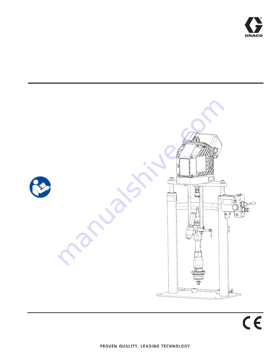
Systems for Sealants 

and Adhesives

For use with non-heated bulk supply of medium to high viscosity sealants and adhesive 
materials. For professional use only.

Not approved for use in explosive atmospheres or hazardous locations. 

D60 3 inch dual post

60 liter (16 gallon) size, 30 liter (8 gallon),
20 Liter (5 gallon) sizes

150 psi (1.0 MPa, 10 bar) Maximum Air Inlet Pressure

See page 3 for model information, including maximum 
working pressure and approvals.

Important Safety Instructions

Read all warnings and instructions in this 
manual and in your pump manual before 
using the equipment. Save all instruc

-

tions.

Summary of Contents for 25E079

Page 1: ...explosive atmospheres or hazardous locations D60 3 inch dual post 60 liter 16 gallon size 30 liter 8 gallon 20 Liter 5 gallon sizes 150 psi 1 0 MPa 10 bar Maximum Air Inlet Pressure See page 3 for mod...

Page 2: ...de 20 Error Codes 20 Ram Troubleshooting 23 Repair 24 Replace Shaft Bearing Assembly 24 Replace Fan Fuses 24 Replace Fan Assembly 25 Replace Electronics Cover 27 Repair Token Cable 30 Software Update...

Page 3: ...es Instruction Parts 312467 100 cc Check Mate Displacement Pump Repair Parts Manual 312468 200 cc Check Mate Displacement Pump Repair Parts Manual 312374 Air Controls Instructions Parts 312491 Pump Fl...

Page 4: ...t can result in amputation Get immediate surgical treatment Engage trigger lock when not dispensing Do not point dispensing device at anyone or at any part of the body Do not put your hand over the fl...

Page 5: ...if static sparking occurs or you feel a shock Do not use equipment until you identify and correct the problem Keep a working fire extinguisher in the work area ELECTRIC SHOCK HAZARD This equipment mus...

Page 6: ...e worn or damaged parts immediately with genuine manu facturer s replacement parts only Do not alter or modify equipment Alterations or modifications may void agency approvals and create safety hazard...

Page 7: ...d Air Controls see FIG 2 H Lift Ring K Driver Disconnect Switch P Pump Bleed Valve R Wet Cup S Driver Pressure Control Knob T Fluid Line not supplied U Air Line not supplied V Air Line Drain Valve not...

Page 8: ...AD Blowoff button AG turns air on and off to push the platen out of an empty drum Air Line Accessories The following accessories are required for proper sys tem operation Air line drain valve V Air li...

Page 9: ...ons where a ground cable could be connected between the electric driver and a metal bucket when flushing a gun into the bucket Air and fluid hoses use only electrically conductive hoses with a maximum...

Page 10: ...nd washers to separate the junction box cover BA and disconnect switch K from the junction box BC on the electrical driver NOTE Inside the junction box fan and power wires are connected to terminals 1...

Page 11: ...the junction box cover and disconnect switch K using the two screws and washers removed in step 2 9 Tighten the cord grip to securely hold the power cord in the junction box Install Vented Oil Cap Be...

Page 12: ...ce ment parts order Kit 255477 The kit includes 2 each of capscrews FA lock washers not shown and drum stops FB 1 Locate the correct set of mounting holes on the ram base 2 Using the capscrews FA and...

Page 13: ...ack off the air regulator to its full counterclockwise position and close all shutoff valves 3 Connect the air line from an air source to the system air inlet See FIG 1 Use a supply hose capable of me...

Page 14: ...gradually then loosen completely Now clear the tip nozzle or hose Flush Before Using Equipment The pump was tested with lightweight oil which is left in the fluid passages to protect parts To avoid co...

Page 15: ...to the ram if the pump does not prime properly with heavier fluids Decrease air pres sure if fluid is forced out around the top seal or platen Change Drums 1 Stop the pump by turning the disconnect s...

Page 16: ...n the sight glass CC See FIG 13 Fill until the oil level is near the halfway point of the sight glass The oil capacity is approximately 1 0 1 2 quarts 0 9 1 1 liters Do not overfill 5 Reinstall the fi...

Page 17: ...elieve ports to remove material residue Adjust Spacers Use Platen with Tapered and Straight Sided Pails The platen is supplied for use with 20 liter 5 gallon 30 liter 8 gallon and 60 liter 16 gallon s...

Page 18: ...y see FIG 18 a For all single wiper platens Remove the two clips 470 with needle nose pliers and remove the platen cover 469 b Remove the eight nuts 459 that hold the wiper assembly to the platen cast...

Page 19: ...r double wiper assemblies Place the bottom plate 455 on a flat surface Place the wiper support 454 wiper 453 spacer 452 wiper 453 and top plate 457 on the bottom plate 455 d Install eight nuts 409 on...

Page 20: ...o forms Alarm alerts you to the alarm cause and shuts down the pump Deviation alerts you to the problem but the pump may continue to run past the set limits until the system s absolute limits are reac...

Page 21: ...is near the maximum operation tem perature The performance has been reduced to prevent the driver from completely shutting down Check fan operation Clean the fan and driver housing Verify the fuses a...

Page 22: ...or to see if the error is still active Contact your Graco distributor or Tech Service for more informa tion 12 13 Alarm Internal Software Error Cycle the power and check the status indicator to see if...

Page 23: ...rod seal Replace See Supply Unit Repair on page 36 Fluid squeezes past ram plate wipers Air pressure too high Decrease Worn or damaged wipers Replace See Remove and Reinstall Wipers on page 18 Pump w...

Page 24: ...screws 53 and remove the junction box cover BA from the driver to gain access to the disconnect block BD Gently pull out the fuse hold ers 4 Unscrew the fuse holder remove the old fuse and replace wit...

Page 25: ...wer wires close to the ferrules NOTE Do not cut the tip off of the ground wire See FIG 20 6 Remove the grounding screw GS and disconnect the green grounding wire coming out of the fan cord grip C1 att...

Page 26: ...G 21 12 Use a ferrule to connect each fan wire to one of the two wires coming out of the motor grommet Then attach one wire set into the disconnect box location 1L1 and the other wire into location 5L...

Page 27: ...wires from locations 1L1 and 5L3 NOTE Power cord cables excluding the ground wire may remain attached 6 Unscrew the ground screws from the fan and power cord ground wires 7 Use a wire cutter to cut fe...

Page 28: ...e stroke position sensor wire SW 15 Disconnect the encoder wire EW 16 Discard the used cover gasket 53 and the junction box gasket 52 FIG 29 Junction Box Sleeve FIG 30 Electronics Cover Removal FIG 31...

Page 29: ...librate correctly 12 Connect the power cord 13 Engage power Driver Motor Encoder Calibration NOTE The driver must be de coupled from the lower and must be able to cycle freely with no obstructions 1 C...

Page 30: ...into the slot NOTE The token has no preferred orientation 5 Tuck the wires back into the junction box BC and reinstall the junction box cover BA with two screws and washers 6 Connect the unit to the...

Page 31: ...e junction box cover BA from the driver to gain access to the token slot TS 10 Remove the token from the slot 11 Tuck the wires back into the junction box BC and reinstall the junction box cover BA wi...

Page 32: ...to service the displacement pump Keep hands and fingers away from the priming piston during operation and whenever the pump is pressur ized to reduce the risk of injury On the pump down stroke the pri...

Page 33: ...p is pressur ized to reduce the risk of injury On the pump down stroke the priming piston extends beyond the intake housing to pull the material into the pump The prim ing piston works under extreme f...

Page 34: ...er Platen NOTE Before installing the 20 30 or 60 liter platen to a pump with an intake adapter install the adapter and o ring from mounting kit 257630 using the two set screws See FIG 45 1 Place the o...

Page 35: ...river by attaching a secure hoist to the driver lift ring H Install Driver 1 Using a secure hoist attach the motor to the mount ing plate 109 with screws 111 and washers 110 See FIG 46 on page 35 2 Fo...

Page 36: ...nd platen will not fall See pages 40 and 42 5 Remove the retaining ring 203 803 6 Remove the piston rod seal and bearing a Slide the end cap 202a pin 202b o ring 202c and spring 202m up and off of the...

Page 37: ...02f 802f washer 202g 802g piston 202e 802e outer o ring 202c 802c and inner o ring 202h 802h 3 Inspect all parts for wear or damage Replace as necessary Assemble Ram Piston 1 Install new o rings 202h...

Page 38: ...p mounting kit and platen are compatible with each driver and supply system Electric Driver Supply System Pump Mounting Kit Platens Gallons liters Pump Mounting Kit Page Platens Page D60 3 in Dual Pos...

Page 39: ...56 124165 SCREW cap socket head 1 69 LABEL branding Xtreme Z45 1 LABEL branding Xtreme Z25 1 96 127721 KNOB impact control preventer 1 97 127463 SCREW cap socket head 1 101 17B505 SLEEVE junction box...

Page 40: ...B D60 3 in Dual Post Supply Unit 216 Detail A Model 257621 Shown 211 212 212 211 203 202a 202c 202d 202b 202j 202k 202m 302n ti21264a 202f 202g 202c 202h 202e Detail A 213 215 217 253 254 255 209 236...

Page 41: ...am 2 202g WASHER split 2 202h O RING 2 202j BEARING ram end cap 2 202k RETAINER retaining ring 2 202m SPRING compression 2 302n 257655 ROD piston ram 2 203 127510 RING retaining 3 06 dia 2 301 RAM 1 2...

Page 42: ...38 for kit configuration table Ref Part Description Qty 381 BRACKET shelf NXT2200 1 BRACKET shelf NXT3400 and NXT6500 382 101533 WASHER spring lock 2 383 101535 NUT hex 2 384 100133 WASHER lock 4 385...

Page 43: ...Platen Single Wiper Platen 465 465 455 456 456 459 462 459 459 461 461 457 454 453 452 469 459 462 470 451 451 r_255648_313527_25a r_255648_313527_26a Single Wiper with SST Platen 455 454 453 460 452...

Page 44: ...ted Nitrile 257641 257730 CS Nitrile 257642 257731 CS PolyUrethane 257643 25A206 SST Nitrile FDA Approved 25A207 257732 30 Liter see page 45 CS Nitrile 257644 257733 CS PolyUrethane 257645 257734 SST...

Page 45: ...6049 1 453 WIPER main 257672 257678 257675 257672 2 257678 2 25A208 1 2 454 WIPER PE support 257681 257681 257681 257681 257681 257681 1 455 PLATE bottom 257668 257668 257671 257668 257668 257671 1 45...

Page 46: ...4 257696 257696 1 453 WIPER main 257674 257680 257677 257674 2 257680 2 1 2 454 WIPER PE support 257683 257683 257683 257683 257683 1 455 PLATE bottom n a n a n a n a n a 1 457 PLATE top n a n a n a n...

Page 47: ...ngle Wiper PTFE 257730 20 L 5 Gal Dual Wiper Nitrile 257731 20 L 5 Gal Dual Wiper Polyurethane 257732 30 L 8 Gal Single Wiper Nitrile 257733 30 L 8 Gal Single Wiper Polyurethane 257734 30 L 8 Gal Sing...

Page 48: ...Wiring Diagram 48 3A5379B Wiring Diagram FIG 50 Wiring Diagram WL D 5 2 5 7 21 72 72 WL E WL D 1 20 1 1 32 5 21752 2 5 32 5 1 32 5 7 7 7...

Page 49: ...Dimensions 3A5379B 49 Dimensions Supply Systems ram up A ram down B E F C D...

Page 50: ...y the maximum weight for each available platen size Ram Model A in mm B in mm C in mm D in mm E in mm F in mm D60 89 2260 6 59 1498 6 14 355 6 18 457 2 24 609 6 28 711 2 Platen Size Gallons Liters Max...

Page 51: ...ted parts For Check Mate displacement pumps see the Check Mate Displacement pumps Instructions Parts manual Air Inlet Sizes D60 3 in dual post 16 gal 60 L 5 gal 20 L 30 gal 115 L 3 4 in npt f Electric...

Page 52: ...material or workmanship repairs will be made at a reasonable charge which charges may include the costs of parts labor and transportation THIS WARRANTY IS EXCLUSIVE AND IS IN LIEU OF ANY OTHER WARRANT...

Reviews: