


3A4096F
EN
Instructions
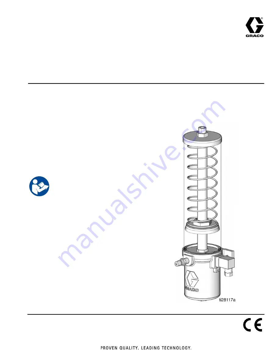
29:1 Lube Pro
™
Vertical Grease
Pump
For pumping non-corrosive and non-abrasive grease only. For professional use only.
Not approved for use in explosive atmospheres or hazardous locations.
Models:
See page 2 for model information, including maximum working
pressure and approvals.
3500psi (24 MPa, 241 bar) Maximum Working Pressure
175 psi (1.2 MPa, 12.07 bar) Maximum Air Input
Pressure
Important Safety Instructions
Read all warnings and instructions in this manual.
Save these instructions.


