background image

308993         11

Operation

Adjust the Spray Pattern

WARNING

INJECTION HAZARD

To reduce the risk of component rupture
and serious injury, including injection, do
not exceed the gun’s maximum fluid

working pressure of 1500 psi (10 MPa, 105 bar) or
the maximum working pressure of the lowest rated
component in the system.

WARNING

COMPONENT RUPTURE HAZARD

Do not exceed the 

maximum fluid and

air pressure

 of this gun. Higher pressur-

es can cause parts to rupture and result in serious
injury.

1.

Do not turn on the air supply yet. Set the fluid
pressure at a low starting pressure. For low vis-
cosity fluids (less than 25 sec, #2 Zahn cup) with
lower percent solids (typically less than 40%), start
at 300 psi (2.1 MPa, 21 bar) at the pump outlet.
For fluids with higher viscosity or higher solids
content, start at 600 psi (4.2 MPa, 42 bar). If a
fluid pressure regulator is installed, use it to make
the adjustments.

If your system does not have a fluid regulator,
such as a Falcon I or Falcon II package, the fluid
pressure is controlled by the air regulator supplying
the pump. See the example below.

Example:

Pump Ratio

x

Pump Air Regulator
Setting

=

Fluid 
Pressure

Falcon I 
(10:1 ratio)

x

30 psi (0.21 MPa,
2.1 bar)

=

300 psi 
(2.1 MPa,
21 bar)

Falcon II 
(20:1 ratio)

x

30 psi (0.21 MPa,
2.1 bar)

=

600 psi 
(4.2 MPa,
42 bar)

2.

Trigger the gun to check the atomization; do not be
concerned about the pattern shape yet.

3.

Increase the fluid pressure in 100 psi (0.7 MPa, 7
bar) increments, just to the point where a further
increase in fluid pressure does not significantly
improve fluid atomization. See the example below.

Example:

Pump 
Ratio

x

Pump Air Regulator
Setting (increments)

=

Fluid 
Pressure
(increments)

Falcon I 
(10:1 
ratio)

x

10 psi (0.07 MPa, 
0.7 bar)

=

100 psi 
(0.7 MPa, 
7 bar)

Falcon II 
(20:1 
ratio)

x

5 psi (0.035 MPa,
0.35 bar)

=

100 psi 
(0.7 MPa, 
7 bar)

4.

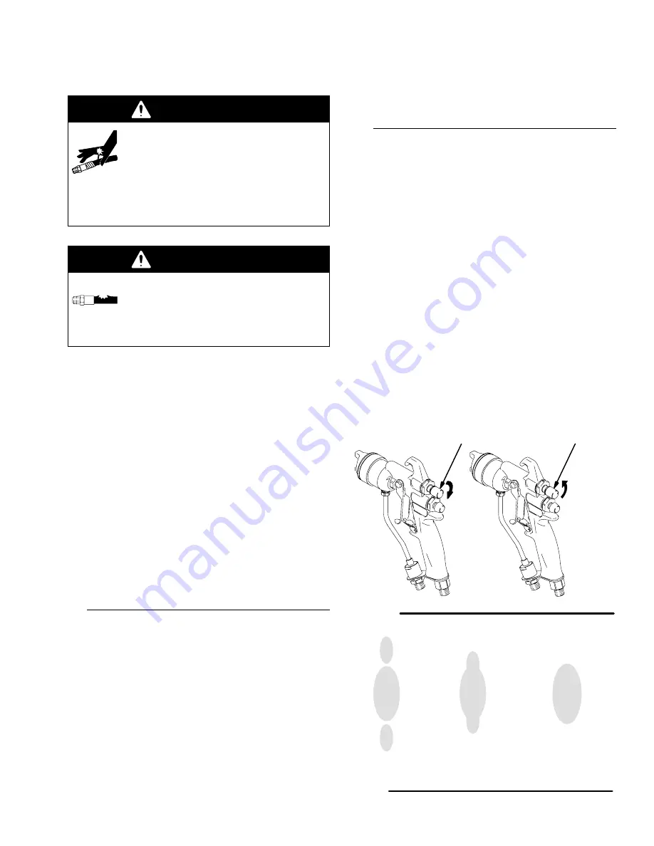
Close off the pattern adjustment air by turning the
knob (S, see Fig. 5) clockwise (in) all the way. This
sets the gun for its widest pattern.

5.

Set the atomizing air pressure at about 5 psi (0.35
bar, 35 kPa) when triggered. Check the spray
pattern, then slowly increase the air pressure until
the tails are completely atomized and pulled into
the spray pattern. See Fig. 6. Do not exceed 100
psi (0.7 MPa, 7 bar) air pressure to the gun.

For a narrower pattern,

 turn the pattern adjustment

valve knob (S, see Fig. 5) counterclockwise (out).
If the pattern is still not narrow enough, increase
the air pressure to the gun slightly or use a differ-
ent size tip.

ÎÎ

ÎÎ

ÎÎ

ÎÎÎ

ÎÎÎ

ÎÎÎ

ÎÎ

ÎÎ

ÎÎ

ÎÎÎ

ÎÎÎ

ÎÎÎ

9131A

Fig. 5

S

Out

(narrower
pattern)

In

(wider
pattern)

S

No Air

Too Little Air

Right Amount

of Air

Fig. 6

0792

Summary of Contents for 241508

Page 1: ...Carbide Ball and Seat Recommended For Pigmented Waterborne and Higher Viscosity Materials Part No 241510 Series A Air Assisted Spray Gun with Plastic Ball and Seat Recommended For Acid Catalyzed Mate...

Page 2: ...nd body glove or rag Do not blow back fluid this is not an air spray gun Check the gun diffuser operation weekly Be sure the gun trigger safety operates before spraying Lock the gun trigger safety whe...

Page 3: ...from rupture caused by kinks or bends near the couplings Use fluids or solvents that are compatible with the equipment wetted parts See the Technical Data section of all the equipment manuals Read the...

Page 4: ...4 308993 Notes...

Page 5: ...42 113 084 226 35 0 35 70 0 7 105 1 05 140 1 4 175 1 75 210 2 10 A B HVLP Gun Models 241509 and 241511 KEY A Fan valve open B Fan valve closed Air Flow Compliant Air Cap 241563 0 1 2 3 4 5 6 7 8 0 5 1...

Page 6: ...A D C B J F G E M H L K N P R Typical Installation The typical installation shown in Fig 1 is only a guide for selecting and installing air assisted spray systems Contact your Graco distributor for a...

Page 7: ...ons 3 Air fluid and hydraulic hoses connected to the pump Use only electrically conductive hoses with a maximum of 500 feet 150 m combined hose length to ensure grounding continuity Check the electric...

Page 8: ...Connect the Fluid Hose NOTE Before connecting the fluid line blow it out with air and flush it with solvent Use solvent which is compatible with the fluid to be sprayed If better control of fluid pre...

Page 9: ...tip the fluid viscosity and the fluid pressure Contact your Graco distributor for assistance in select ing an appropriate spray tip for your application Refer to the Tip Selection Chart on page 28 Acc...

Page 10: ...ompletely clogged or that pressure has not been fully re lieved after following the steps above very slowly loosen the air cap retaining ring to relieve pressure in the cavity between the ball seat sh...

Page 11: ...MPa 2 1 bar 300 psi 2 1 MPa 21 bar Falcon II 20 1 ratio x 30 psi 0 21 MPa 2 1 bar 600 psi 4 2 MPa 42 bar 2 Trigger the gun to check the atomization do not be concerned about the pattern shape yet 3 In...

Page 12: ...10 psi 70 kPa 0 7 bar Remove the verification kit air cap and install Air Cap 241563 Apply the Fluid Always hold the gun at a right angle from the surface Do not make an arc with the gun as it causes...

Page 13: ...TION Solvent left in gun air passages could result in a poor quality paint finish Do not use any cleaning method which may allow solvent into the gun air passages 02055 02027 Do not immerse the gun in...

Page 14: ...ap 14 and spray tip 33 3 Disconnect the fluid supply hose H and air supply hose J from the gun 9123A Fig 8 H J 18 14 33 4 Connect the solvent supply hose T to the gun 9124A Fig 9 T 5 Increase the pres...

Page 15: ...an the air cap retaining ring 18 air cap 14 and seat housing 13 with solvent 11 Dip the end of a soft bristle brush into a compatible solvent Do not continuously soak the brush s bristles with solvent...

Page 16: ...g 18 air cap 14 and spray tip 33 Fig 16 Plastic seat housing Torque to 125 135 in lb 14 15 N m Carbide seat housing Torque to 155 165 in lb 17 18 N m 1 9119A 1 13 12b 36 18 14 33 16 Dampen a soft clot...

Page 17: ...whenever the seat assembly is removed If plastic replace the plastic seat 13a in the seat assembly 13 The gasket 12b must be replaced when ever the seat assembly is removed Fluid in air passages Spray...

Page 18: ...or or fill fluid supply tank Check tighten pump siphon hose connections bleed air from paint line Cannot feather with an AA gun Feathering will cause drastic reduc tion of pressure at the tip resultin...

Page 19: ...quipment and when ever you are instructed to relieve pressure 1 Relieve the pressure 2 Unscrew the fan valve packing nut A from the back of the gun body 1 Slide the fan valve assembly 28 out of the gu...

Page 20: ...y 13 from the gun body 1 using the gun tool 36 Remove and discard the seat assembly gasket 12b NOTE Always install a new seat gasket 12b when ever you remove the seat assembly 13 5 Remove the trigger...

Page 21: ...Lightly lubricate the o rings Also lubricate the needle shaft where the packing slides 5 Insert the fluid needle assembly 12 into the front of the gun Use the tool 12c to push the packing cartridge in...

Page 22: ...th a notch on the outer edge faces the cartridge 13b Torque the cartridge to 85 95 in lb 9 6 10 7 N m 10 Install a new seat gasket 12b Trigger the gun to pull the needle back while you screw the seat...

Page 23: ...eable On Models 241510 and 241511 torque to 85 95 in lb 9 6 10 7 N m Always install a new seat gasket 12b when ever you remove the seat assembly 13 U cup lips face away from gun body 1 Plastic seat ho...

Page 24: ...y 1 16 194749 SEPARATOR air 1 17 107079 O RING PTFE 1 18 241483 RING air cap retaining includes replaceable item 18a 1 18a 192760 U CUP 1 19 192271 TRIGGER 1 20 203953 SCREW trigger lock 1 21 192272 P...

Page 25: ...2c 13 14 16 17 18 18a 19 20 21 22 23 24 25 26 27 28 28 Ref 28a 28b 33 34 36 12 33a 33b 4 5 308993 25 Parts Part No 241508 Air Assisted Spray Gun with Carbide Ball and Seat Part No 241509 HVLP Spray Gu...

Page 26: ...item 18a 1 18a 192760 U CUP 1 19 192271 TRIGGER 1 20 203953 SCREW trigger lock 1 21 192272 PIN pivot 1 22 188493 U CUP UHMWPE 1 23 241503 AIR VALVE ASSEMBLY 1 24 194563 EXTENSION needle 1 25 114069 SP...

Page 27: ...4 16 17 18 18a 19 20 21 22 23 24 25 26 27 28 28 Ref 28a 28b 33 12 13a 13b 12c 34 36 33b 33a 4 5 308993 27 Parts Part No 241510 Air Assisted Spray Gun with Plastic Ball and Seat Part No 241511 HVLP Spr...

Page 28: ...GW413 10 12 250 300 GGW513 12 14 300 350 GGW613 14 16 350 400 GGW713 Orifice Size Fan Width at 12 Fluid Output Fluid Output Part No Size inches mm at 12 300 mm Inches Output Light to Medium Output Hea...

Page 29: ...2 14 300 350 GGW619 14 16 350 400 GGW719 16 18 400 460 GGW819 18 20 457 508 GGW919 Orifice Size Fan Width at 12 Fluid Output Fluid Output Part No Size inches mm at 12 300 mm Inches Output Light to Med...

Page 30: ...luid Hose 241812 3500 psi 24 MPa 242 bar Maximum Working Pressure 1 4 18 npsm fbe 3 16 in 5 mm ID 25 ft 7 62 m long nylon tubing with polyurethane cover Accessory Air Cap 241882 For use with low visco...

Page 31: ...s Sound Pressure at 20 psi 140 kPa 1 4 bar 63 8 dB A Sound Pressure at 100 psi 0 7 MPa 7 bar 79 7 dB A Sound Power at 20 psi 140 kPa 1 4 bar 74 9 dB A Sound Power at 100 psi 0 7 MPa 7 bar 90 9 dB A We...

Page 32: ...buyer agrees that no other remedy including but not limited to incidental or consequential damages for lost profits lost sales injury to person or property or any other incidental or consequential lo...

Reviews: