background image

Operation

308687L

7

Changing the Measurement Units and 
Calibration Factor

NOTE: A

 one liter Weights and Measures approved 

container is required for calibration.

This meter is factory calibrated to dispense 10W-30 
motor oil at 70_ F (21_ C) at 2.0 gpm (7.6 lpm) and is 
acceptably accurate for most common fluids over a 
typical temperature range. If you will use the meter to 
dispense antifreeze or other approved fluids, you may 
have to recalibrate it for greater accuracy.

1. Press and hold both the 

TOTAL

 and 

RESET

 but-

tons for four seconds. 

The numbers on the display turn off, and the

 L

 (for 

liters) and 

CAL

 (for calibration) icons turn on.

2. Set the units of measurement by repeatedly press-

ing the 

RESET

 button until the correct unit of mea-

surement is displayed. See the list below:

GAL = gallons
QTS = quarts
PTS = pints
L

 = liters

3. Press the 

TOTAL

 button to go to the CALIBRA-

TION menu.

NOTE:

 If you do not want to change the calibration 

factor, press the 

TOTAL

 button again to use the 

existing calibration factor and to resume normal 
operation. 

To change the calibration factor, 

do 

steps


4 and 5.

4. Dispense exactly one liter of fluid into a calibrated 

1-liter container. For proper calibration, you must 
dispense exactly 1 liter according to the markings 
on the container.

NOTE: I

f you dispense more than 1 liter, press the 

TOTAL

 button to exit the CALIBRATION menu. 

Pressing the 

TOTAL

 button at this point does not 

save the new calibration factor. You must complete 
steps 1 to 5 change the calibration factor.

5. Press the 

RESET

 button to store the new calibra-

tion factor and resume normal operation.

NOTE: 

The number on the display is the calibration 

factor number. It must be in the range of 311 to 
466. The following table lists approximate calibra-
tion factors for different fluids. Your calibration 

number may vary slightly due to temperature or 
flow rate.

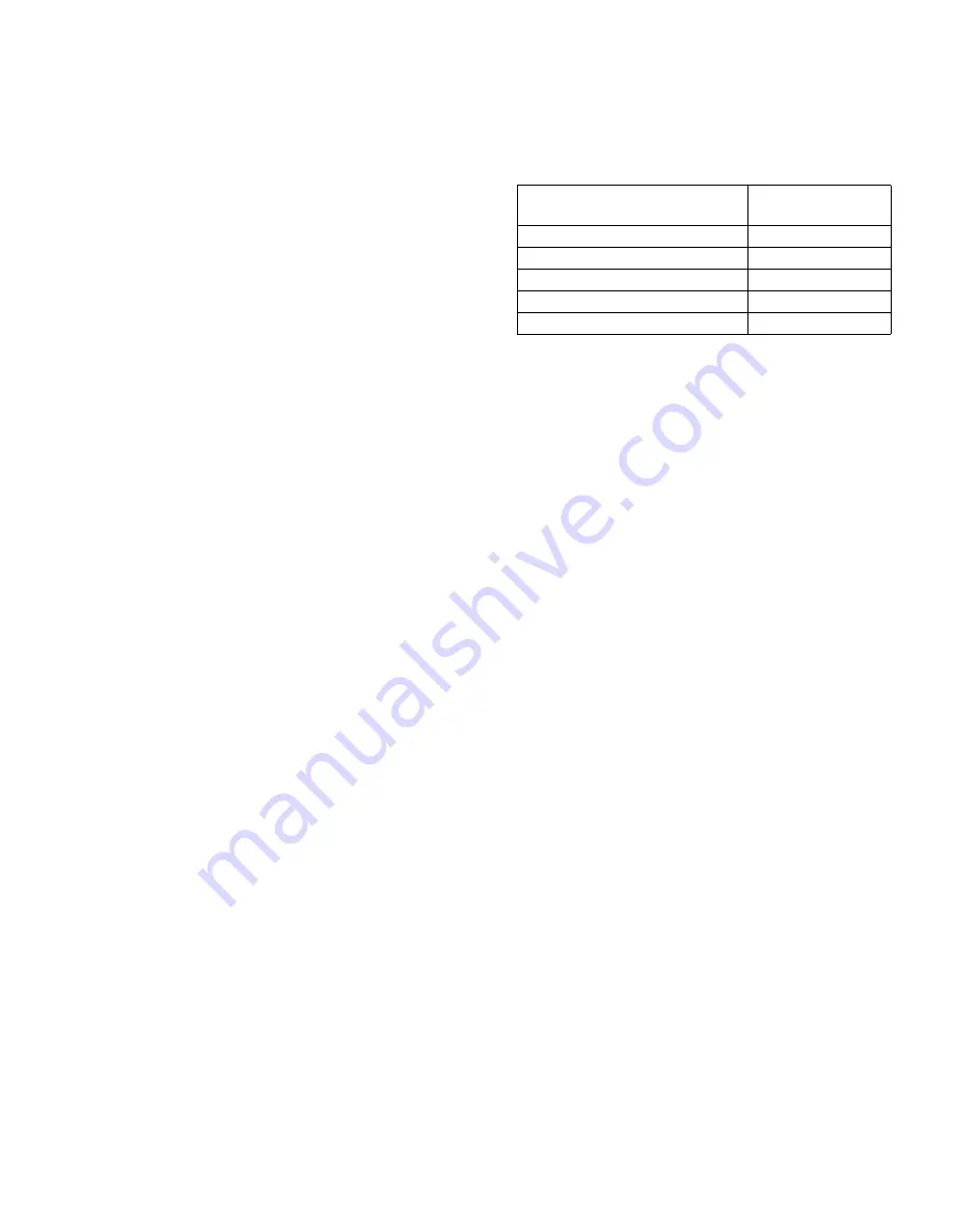
Calibration factors at 70°F (21°C) at 2.0 gpm (7.6 lpm)

Fluid

Calibration 

Number

oil (10W-30)

389

gear lube

389

automatic transmission fluid

389

antifreeze

367

windshield washer solvent

341

Summary of Contents for 239824

Page 1: ...h petroleum based and synthetic oil antifreeze and windshield washer fluid only Model 239824 500 psi 3 4 MPa 34 bar Maximum Working Pressure 5 gpm 19 lpm Maximum Flow Rate Important Safety Instructions Read all warnings and instructions in this manual Save these instructions ...

Page 2: ...ment Tighten all fluid connections before operating the equipment Check hoses and couplings daily Replace worn or damaged parts immediately FIRE AND EXPLOSION HAZARD When flammable fluids are present in the work area such as gasoline and windshield wiper fluid be aware that flammable fumes can ignite or explode To help prevent fire and explosion Use equipment only in well ventilated area Eliminate...

Page 3: ...turer s replacement parts only Do not alter or modify equipment Alterations or modifications may void agency approvals and cre ate safety hazards Make sure all equipment is rated and approved for the environment in which you are using it Use equipment only for its intended purpose Call your distributor for information Route hoses and cables away from traffic areas sharp edges moving parts and hot ...

Page 4: ...red Part No 235998 Install downstream from the pump C In line filter D In line electronic meter All electrical wiring must be done by a qualified elec trician and comply with all local codes and regula tions Do not use the IM5 In line Electronic Meter in sys tems where the operating pressure exceeds the max imum pressure of the meter or any other component in the system NOTICE Do not use PTFE tape...

Page 5: ...rt of the dispense valve firmly to the side of a grounded metal pail then trigger the valve Factory Settings The meter is factory calibrated for 10W 30 oil and the default unit of measurement is quarts For other fluids and different units of measurement see Changing the Measurement Units and Calibration Factor on page 8 The equipment must be grounded to reduce the risk of static sparking Static sp...

Page 6: ...ed total is shown in gallons when the unit of measurement is set in gallons quarts or pints The accumulated total is shown in liters when the measure ment is set in liters The meter accumulates a running total of up to 99 999 gallons or liters dispensed before returning to zero See Fig 3 Function of RESET Press and hold the RESET key to clear the digital dis play after each dispense cycle NOTE Alw...

Page 7: ...e calibration factor press the TOTAL button again to use the existing calibration factor and to resume normal operation To change the calibration factor do steps 4 and 5 4 Dispense exactly one liter of fluid into a calibrated 1 liter container For proper calibration you must dispense exactly 1 liter according to the markings on the container NOTE If you dispense more than 1 liter press the TOTAL b...

Page 8: ... electronic components of the control Do not remove the black cover over the electronic area when you replace the battery There are no user replaceable components under this cover Do not lay anything on the electronics Do not twist or force parts Align parts properly as instructed To avoid malfunction or high pressure fluid spray do not remove the metal cover of the metering unit There are no user...

Page 9: ...ering unit 4 together Torque the screws to 15 20 in lb 1 7 to 2 3 N m or until no gap exists between the electronic control and the metering unit Electronic Control Replacement Procedure FIG 6 1 Relieve Pressure see procedure in previous sec tion 2 Remove the four screws 3 holding the electronic control 1 and metering unit 4 together 3 Remove the battery See Battery Replacement Procedure in the pr...

Page 10: ...lastic housing 8 Install the four screws 3 holding the electronic control 1 to the metering unit 4 together Torque the screws to 15 20 in lb 1 7 to 2 3 N m or until no gap exists between the electronic control and the metering unit NOTICE To avoid pinching the battery wires install the bat tery as shown in FIG 5 The battery wire should extend to the far side of the battery compartment NOTICE Closi...

Page 11: ...Battery is low Replace the battery See Battery Replacement Procedure page 9 and Technical Data page 13 for recommended battery Electronic control is malfunctioning Replace electronic control See Electronic Control Replacement Procedure page 9 There is no fluid flow Metering unit is malfunctioning Replace the meter Strainer if used is clogged Remove and clean or replace strainer using Strainer Kit ...

Page 12: ...er before the meter or before the valve on the meter valve combination Install the o ring after the strainer to hold the strainer in place See FIG 9 Thermal Relief Kit 235998 1 2 14 npt m x 1 2 14 npt f Install downstream from the pump FIG 7 Ref Part Description Qty 1 245598 CONTROL electronic 1 2 113930 GASKET 1 3 113941 SCREW 4 4 UNIT metering cannot be sold separately 1 Screws 3 and Gasket 2 ar...

Page 13: ...x accuracy is 1 25 percent Repeatability 0 15 percent Measured at 2 5 gpm 9 5 lpm at 70 F 21 C with 10 weight oil and 1 gallon dispensed Inlet Outlet Meter can be installed with flow in either direction 1 2 npt Temperature Operating temperature range 4 F to 122 F 20 C to 50 C Storage temperature range 13 F to 122 F 25 C to 50 C Materials of Construction Wetted parts nickel zinc LCP nitrile rubber ...

Page 14: ...rial or workmanship repairs will be made at a reasonable charge which charges may include the costs of parts labor and transportation THIS WARRANTY IS EXCLUSIVE AND IS IN LIEU OF ANY OTHER WARRANTIES EXPRESS OR IMPLIED INCLUDING BUT NOT LIMITED TO WARRANTY OF MERCHANTABILITY OR WARRANTY OF FITNESS FOR A PARTICULAR PURPOSE Graco s sole obligation and buyer s sole remedy for any breach of warranty s...

Reviews: