background image

5

307-922

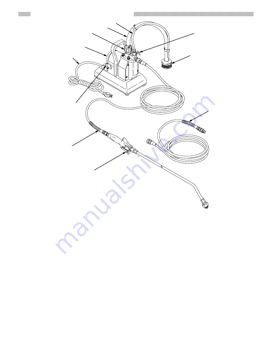
MINI-WETTER SYSTEM DESCRIPTION

SUCTION HOSE

PRIMING TUBE

INLET VALVE

MOTOR

ON/OFF SWITCH

POWER SUPPLY CORD

PRIMING VALVE

50 FT. (15 M) HOSE

SPRAY WAND

STRAINER

50 FT. (15 M) HOSE

0335

0285

Motor
The motor drives the connecting rod which moves the

diaphragm.

Pressure Switch
The pressure switch at the pump outlet turns the motor

on and off to control material pressure.

Diaphragm
The diaphragm is the heart of the pump. Driven by the

connecting rod and motor , the movement of the  dia-

phragm draws material through the suction hose and to

the outlet valve.

Priming Valve
The priming valve assists in priming the pump during

startup.  Turning the priming valve 

counterclockwise

causes the material to drain directly back into the pail

through the priming tube. T urning the knob 

clockwise

causes the  to flow through the fluid outlet valve and to

the hose and spray valve.

Outlet Valve
The outlet valve has a ball check which prevents material

from flowing backwards into the pump. This helps keep

an even supply of material to the roller each time you trig-

ger the spray valve.

Inlet Valve
As the diaphragm draws material from the suction tube,

the  material passes through the inlet valve which opens

to allow material into the pump.

Outlet Hose
The hoses have swivel-type couplings for easy assem-

bly. A larger diameter outlet hose and chemical-resistant

outlet and suction hoses are available. See ACCESSO-

RIES on page 19.

Spray Valve
The spray valve controls material flow by triggering it on

and off.

Summary of Contents for 222-340

Page 1: ...ration 7 Maintenance Flushing 8 Roller Cover 9 Troubleshooting Chart 10 Repair Roller Valve 11 Fuse 12 ON OFF Switch 12 Rectifier 12 Power Supply Cord 12 Pressure Switch 13 Outlet Valve 13 Inlet Valve...

Page 2: ...static sparking Read and follow the grounding instructions on page 6 of this manual EQUIPMENT MISUSE HAZARD This system is designed to be used at 250 psi 17 5 bar MAXIMUM WORKING PRESSURE Use only com...

Page 3: ...ltant des tincelles d lectricit statique Lisez et observez les instuctions de mise la terre la page 6 de ce manuel DANGERS POUVANT RESULTER DU MAUVAIS USAGES DE L EQUIPMENT Ce syst me est con u pour t...

Page 4: ...oque el ctrico u otras lesiones corporales graves debido a chispas est ticas Leer y seguir las instrucciones dadas en la p gina 6 de este manual PELIGRO POR MAL USO DEL EQUIPO Este sistema est dise ad...

Page 5: ...ming valve counterclockwise causes the material to drain directly back into the pail through the priming tube T urning the knob clockwise causes the to flow through the fluid outlet valve and to the h...

Page 6: ...the power supply cord Be sure the outlet is properly grounded In the event of an electrical short circuit grounding reduces the risk of an electric shock by providing an escape wire for the electric c...

Page 7: ...ute shut it off Heavy viscosity material may need to be thinned Be sure to follow the material manufacturer s recommendations on thinning 6 Trigger the spray valve to prime the outlet hose and extensi...

Page 8: ...e material is drained This avoids contaminating the material with the flushing water 3 Now hold the spray wand over the flushing pail Turn on the pump and trigger the spray valve Circulate the solutio...

Page 9: ...9 307 922 NOTES...

Page 10: ...and try to prime sys tem If it doesn t prime in one minute replace the out let spring See Outlet Valve page 14 Inlet valve stuck or damaged Depress valve gently and pour in about 1 teaspoon mineral s...

Page 11: ...the assem bly tool M and press the lips of the packing over the end of the tool See Fig 6 10 Guide the tool M into the fluid housing D until the needle protrudes through the bottom of the housing Lig...

Page 12: ...e terminal ON OFF Switch See Fig 8 and 9 1 Disconnect the two leads from the ON OFF switch 34 terminals See Fig 9 2 Remove the boot 36 and pull the switch 34 out of the base Remove the ground wire 84...

Page 13: ...oroughly clean and dry all parts 6 Tip the pump back Install a new seal 2f making sure it lays flat 7 Install the seat 2e and torque it to 80 100 in lb 13 5 16 N m 8 Drop in the ball 2d making sure it...

Page 14: ...otor shaft D to be sure it turns freely 9 Reinstall the front cover 23 Priming Valve Tube See Fig 13 NOTE Each new priming valve kit includes a priming tube and fittings 1 Unscrew the nut on the handl...

Page 15: ...again CAUTION Spinning the motor shaft while assembling the pump ensures that parts are properly aligned If they are not and you start the pump serious damage could result to the motor bearing and co...

Page 16: ...CATE TORQUE TO 85 in lb 9 6 N m SEE DETAIL A page 17 PRESS FIT INTO 22 34 68 67 28 43 33 33 39 25 26 69 36 30 32 44 47 45 46 15 16 22 11 17 48 49 27 21 20 18 23 24 29 LABEL 96 LABEL 0301 52 54 LABEL 4...

Page 17: ...rod Always order two of Ref No 27 when replacing housing 1 23 181 166 COVER front 1 24 108 236 SCREW mach filh No 8 32 x 0 312 4 25 102 313 CAPSCREW hex head 1 4 20 x 1 75 2 26 100 028 LOCKWASHER int...

Page 18: ...ng 2 85 108 228 NIPPLE 3 8 npt 1 87 108 408 ADAPTER 1 88 220 237 WAND tube 1 REF NO PART NO DESCRIPTION QTY 89 186 334 ADAPTER tip 1 90 171 602 WASHER tip 1 91 185 559 431 SPRAY TIP 0 031 orifice 1 92...

Page 19: ...e than 25 ft 7 6 m of outlet hose Not intended for use with lacquer or lacquer thinners 220 009 Outlet Hose 3 8 ID cpld 3 8 npsm fbe 50 15 m FIXED EXTENSION TUBES Included with sprayer 12 in 0 31 m lo...

Page 20: ...ment of structures accessories equipment or materials not supplied by Graco or the improper design manufacture installation operation or maintenance of structures accessories equipment or materials no...

Reviews: