background image

Operation 

8

306565K

Operation

Pressure Relief Procedure

1.

Close the bleed-type air shutoff valve (SV) to relieve 
pressure to the air motor. 

2.

Disconnect the air line. 

Find the Proper Agitator Speed

NOTE: There must be proper continuity between 
agitator and a ground before operating. See 
Grounding, page 7.

1.

Fill the fluid supply container to about 3 or 4 inches 
(75–100 mm) above the agitator blade. Periodically 
check fluid level.

2.

Start the agitator, and gradually increase the speed by 
turning the needle valve (2) until a vortex begins to 
form in the paint.

3.

Reduce the speed slightly, then fill the fluid 
container. Use the lowest agitator speed needed for 
thorough agitation of the paint. Excessive agitator 
speed may cause the paint to foam.

NOTE: Use liquids with conductivity greater than 1000 
pS/m.

NOTE: If an air shutoff valve (SV) is installed in the 
supply line and used to stop the agitator, the same 
agitator speed will be set each time the agitator is used 
without repeating the procedure described above. 

Operating the Agitator

Operate the agitator continuously while supplying paints 
or other fluids to the system. Use the needle valve (2) to 
regulate the agitator speed. Set the agitator speed to 
thoroughly mix the paint, using the lowest speed 
possible.

To stop the agitator, close the bleed-type air shutoff 
valve (SV) in the air supply line or close the needle valve 
(2).

Stop the agitator before removing from pail.

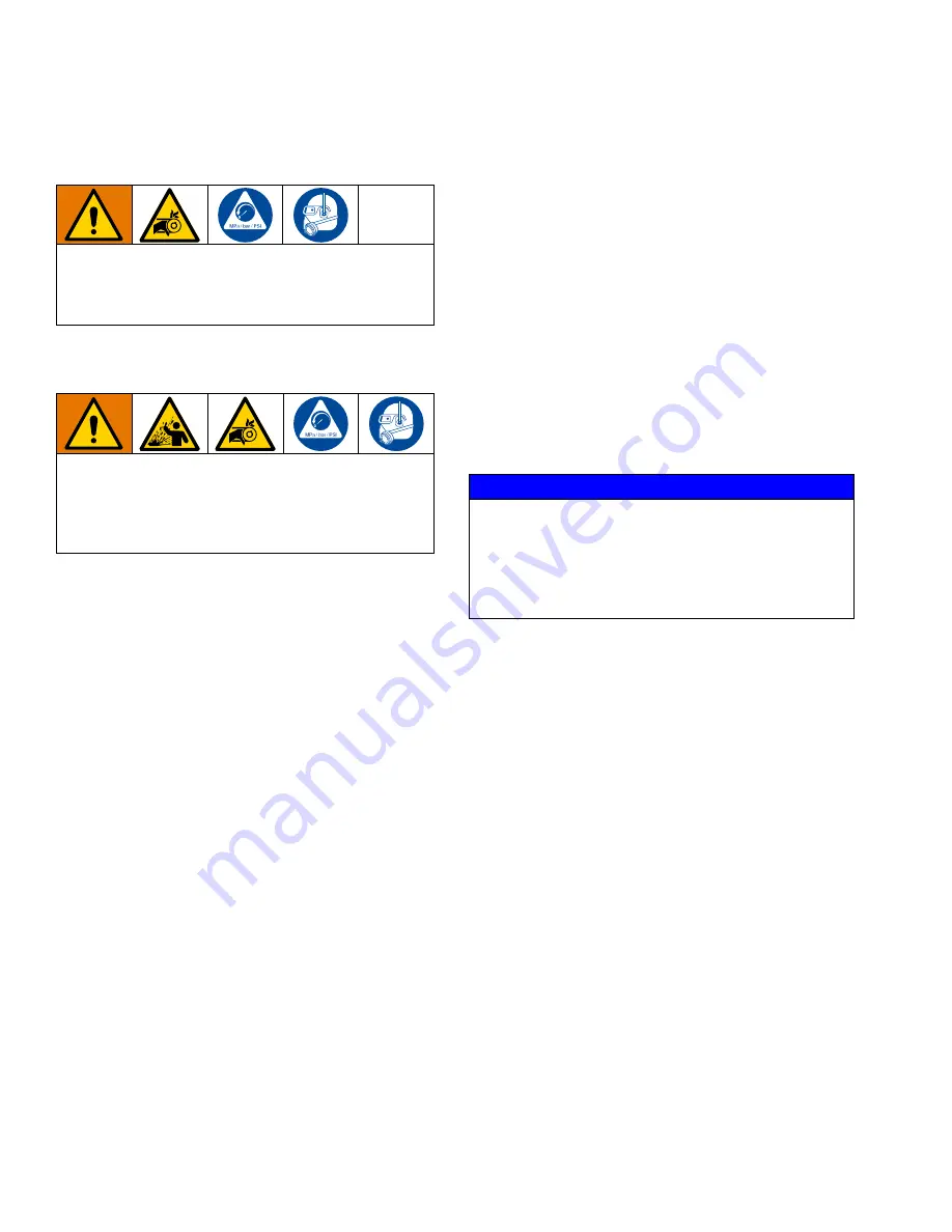
Moving parts, such as an impeller blade, can cut or 
amputate fingers. To reduce the risk of serious injury, 
always shut off the agitator and disconnect the air line 
before moving, checking, or repairing the agitator.

This equipment stays pressurized until pressure is 
manually relieved. To help prevent serious injury from 
splashing fluid and moving parts, follow the Pressure 
Relief Procedure before cleaning, checking, or 
servicing the equipment.

NOTICE

To avoid damaging the equipment, do not operate the 
agitator at a high speed for a long period of time. 
Excessive agitator speed can cause foaming of fluid 
(making the fluid unusable), vibration, and increased 
wear on parts. Only agitate the fluid enough to 
maintain even mixing.

Summary of Contents for 204536

Page 1: ...s For professional use only 100 psi 0 7 MPa 7 bar Maximum Working Pressure See page 2 for model information including maximum working pressure and approvals Important Safety Instructions Read all warn...

Page 2: ...4536 224571 224572 Stainless Steel Agitators 12 Dimensions 14 Technical Specifications 15 California Proposition 65 15 Graco Standard Warranty 16 Models Agency Approvals Model Maximum Working Pressure...

Page 3: ...and gasoline Do not plug or unplug power cords or turn power or light switches on or off when flammable fumes are present Use only grounded hoses Hold gun firmly to side of grounded pail when triggeri...

Page 4: ...y approvals and create safety hazards Make sure all equipment is rated and approved for the environment in which you are using it Use equipment only for its intended purpose Call your distributor for...

Page 5: ...3 8 npt f 208392 3 8 npt f x 1 4 npt m 208393 3 8 npt m x 3 8 npt m Install an air line filter AF to remove harmful dirt and moisture from the air supply To order an air line filter order part number...

Page 6: ...5 onto the agitator shaft 12 or 13 Apply anaerobic sealant and torque nut 5 See Parts page 12 Model 204536 Screw the straight tube fitting 14a into the needle valve s 2 1 8 npt inlet See FIG 2 Screw...

Page 7: ...See FIG 3 Secure the ground wire terminal C to the agitator with the screw and lockwasher Connect the other end of the ground wire to a true earth ground To order a ground wire assembly order part num...

Page 8: ...repeating the procedure described above Operating the Agitator Operate the agitator continuously while supplying paints or other fluids to the system Use the needle valve 2 to regulate the agitator sp...

Page 9: ...is compatible with the spray material and the surfaces being cleaned Additionally extra precautions need to be taken if using lower conductive materials 1000 pS m such as Avoid stirring mixing at hig...

Page 10: ...present in the motor chamber an experienced mechanic may remove the end plate opposite the drive shaft end New vanes should have the edges with cut corners or the notched edges if the vanes are rever...

Page 11: ...Service 306565K 11...

Page 12: ...Includes items 2 to 12 MODEL 204536 ONLY 14b 14c Ref 14 Tube Assembly Includes items 14a to 14c 14a 15 MODEL 204536 ONLY Ref 15 Hose 1 Apply medium grade sealant to external threads 2 Press fit 7 9 2...

Page 13: ...164700 BODY valve 1 2d 166531 WASHER nylon 1 2e KNOB adjustment 1 2f 166532 NUT packing 1 3 110272 SET SCREW schd cup pt 1 420 x 1 4 SST 2 4 103975 LOCKWASHER spring 3 8 in SST1 1 5 110271 NUT hex cap...

Page 14: ...Dimensions 14 306565K Dimensions 3 12 in 80 mm 3 12 in 80 mm 13 25 in 337 mm 17 25 in 433 mm MODELS 204536 222695 Agitators for 5 gallon pail MODEL 224572 Agitator for 10 gallon pail...

Page 15: ...a 7 bar 800 RPM normal load Sound pressure level Sound power level 65 3 dBa 78 6 dBa Noise level at 100 psi 0 7 MPa 7 bar max RPM no load Pressure level Power level 87 3 dBa 100 7 dBa Tested to CAGI P...

Page 16: ...at a reasonable charge which charges may include the costs of parts labor and transportation THIS WARRANTY IS EXCLUSIVE AND IS IN LIEU OF ANY OTHER WARRANTIES EXPRESS OR IMPLIED INCLUDING BUT NOT LIM...

Reviews: