background image

Related Manuals 

2

313212B

Contents

Related Manuals   . . . . . . . . . . . . . . . . . . . . . . . . . . .  2

Overview . . . . . . . . . . . . . . . . . . . . . . . . . . . . . . . . . .  2

Installation  . . . . . . . . . . . . . . . . . . . . . . . . . . . . . . . .  3

Location   . . . . . . . . . . . . . . . . . . . . . . . . . . . . . . .  3

Mount the Enclosure  . . . . . . . . . . . . . . . . . . . . . .  3

Install the Cable   . . . . . . . . . . . . . . . . . . . . . . . . .  4

Install the Air Flow Switch  . . . . . . . . . . . . . . . . . .  5

Install the Pressure Switch  . . . . . . . . . . . . . . . . .  6

Install the Solenoid  . . . . . . . . . . . . . . . . . . . . . . .  7

Connect the Cable to the RoboMix Control Board 8

Connect the Gun Flush Box   . . . . . . . . . . . . . . . .  9

Connect Air Supply to Module   . . . . . . . . . . . . . .  9

Replace the Cover   . . . . . . . . . . . . . . . . . . . . . . .  9

Ground the Enclosure  . . . . . . . . . . . . . . . . . . . . .  9

Parts  . . . . . . . . . . . . . . . . . . . . . . . . . . . . . . . . . . . .  11

Connect a Booth Control to the RoboMix 

(to operate as a manual system)  . . . . . . . . . .  12

Dimensions   . . . . . . . . . . . . . . . . . . . . . . . . . . . . . .  13

Technical Data  . . . . . . . . . . . . . . . . . . . . . . . . . . . .  13

Graco Standard Warranty  . . . . . . . . . . . . . . . . . . .  14

Graco Information    . . . . . . . . . . . . . . . . . . . . . . . .  14

Related Manuals

See the following manuals for additional information on 
the ProMix 2KS and Gun Flush Box Kits.
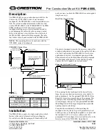
Overview

Gun Flush Box Interface Kit 15V534 provides electrical 
and air connections to enable a ProMix 2KS RoboMix 
proportioner to operate one or two gun flush boxes. See 
F

IG

. 1 for the identification label.

Order Gun Flush Box Kit 15V826 separately (see man-
ual 312784). Each 15V826 Kit includes one gun flush 
box and related parts. The pressure switch, air flow 
switch, and solenoid valve included in Gun Flush Box Kit 
15V826 will be installed in this interface module.

Manual

Description

312778

ProMix 2KS Automatic System 
Installation

312779

ProMix 2KS Automatic System 
Operation

312780

ProMix 2KS Automatic System 
Repair-Parts

312784

Gun Flush Box Kits

F

IG

. 1. GFB Interface Module Identification Label

.7

7

100

MAX AIR WPR

MPa

bar

PSI

GFB CONTROL MODULE

ProMix™ 2KS

PART NO.

SERIES

SERIAL

Artwork No. 293514 Rev. C

GRACO INC.
P.O. Box 1441
Minneapolis, MN 
55440 U.S.A.

C

US

Intrinsically safe equipment
for Class I, Div 1, Group D, T3
Ta = -20°C to 50°C
Install per 289833

FM08ATEX0073
II 2 G
Ex ia IIA T3

Summary of Contents for 15V534

Page 1: ...d in conjunction with ProMix 2KS Electronic Proportioners 100 psi 0 7 MPa 7 bar Maximum Air Input Pressure Important Safety Instructions Read all warnings and instructions in this manual For complete...

Page 2: ...nnections to enable a ProMix 2KS RoboMix proportioner to operate one or two gun flush boxes See FIG 1 for the identification label Order Gun Flush Box Kit 15V826 separately see man ual 312784 Each 15V...

Page 3: ...ent height for the operator and so equipment is easily accessi ble for maintenance 4 Drill mounting holes in the wall Install anchors as needed 5 Bolt equipment securely To avoid electric shock ground...

Page 4: ...of the 10 position connector 24 and pins 1 4 of the 6 position connector as shown in the Cable 23 Wire Harness Detail on page 11 FIG 2 Connect Cable to Terminal Strip 20 12 TI14279a 7 Table 1 Terminal...

Page 5: ...he switch es in the right side of the enclosure See FIG 3 2 Connect the wires from AFS 1 to the right side of the terminal strip 12 pins 1 2 as indicated by the label 21 See FIG 4 and Table 1 3 If usi...

Page 6: ...stall the switch es in the left side of the enclosure See FIG 5 2 Connect the wires from PS 1 to the right side of the terminal strip 12 pins 5 6 as indicated by the label 21 See FIG 6 and Table 1 3 I...

Page 7: ...remove the two sealing screws 4 from the solenoid manifold 8 before installing SO 2 Also remove the plug 5 from the connector 15 2 Connect the wires from SO 1 to the right side of the terminal strip...

Page 8: ...24 to J1 on the control board See FIG 9 3 Connect the 6 position connector 25 to J8 on the control board See FIG 10 NOTICE To avoid damaging circuit board when servicing wear grounding strap on wrist...

Page 9: ...zing air safety shutoff valve IN port See the gun flush box manual for details on the safety shutoff valve Connect Air Supply to Module Connect a 1 4 in 6 mm OD tube between a clean dry air supply fil...

Page 10: ...Installation 10 313212B...

Page 11: ...art No Description Qty 1 15V531 ENCLOSURE GFB module 1 3 118435 GROMMET 1 4 121628 SCREW self sealing 4 5 113279 PLUG fitting tube 1 6 116343 SCREW ground 1 7 114421 BUSHING strain relief 1 8 15V533 M...

Page 12: ...ent location near the RoboMix Bring the cable to the RoboMix and thread it through the cable path at the back 2 See the ProMix 2KS Repair Parts manual Open the RoboMix to access the control board 3 Co...

Page 13: ...6 75 in 171 5 mm 7 50 in 190 5 mm 6 28 in 159 5 mm 4 00 in 101 6 mm 4 00 in 101 6 mm Mounting Holes Maximum Air Input Pressure 100 psi 0 7 MPa 7 bar Air Inlet Size 1 4 in 6 mm OD tube connector Air O...

Page 14: ...rkmanship repairs will be made at a reasonable charge which charges may include the costs of parts labor and transportation THIS WARRANTY IS EXCLUSIVE AND IS IN LIEU OF ANY OTHER WARRANTIES EXPRESS OR...

Reviews: