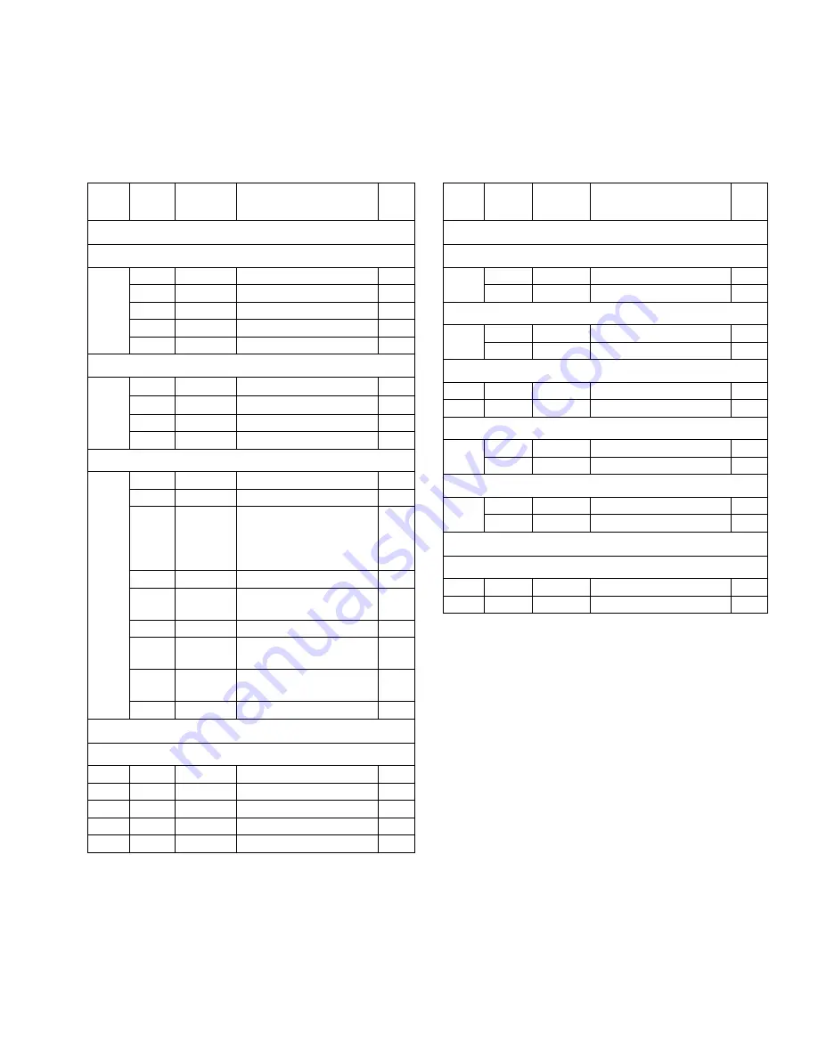
background image

Parts List

310622L

27

Parts List

Pump Configuration Parts List

* Indicates replacement parts.

Inlet and Outlet Parts List

* Indicates replacement parts.

Digit Ref. 

No.

Part No. Description

Qty

Model 3150

A

3A Approved Ball Check

132

510490

CLAMP, 4 in.

4

2XB

15H406

SEAT

4

234

249533

COVER, fluid

2

240*

15H460

GASKET, 4 in., EPDM

12

2XA

15H407

STOP, ball

4

B

Ball Check

233

15D026

SEAT

4

234

234530

COVER, fluid

2

240*

15H460

GASKET, 4 in., EPDM

4

242*

15D346

GASKET, ball stop

4

F

Flapper Check

234

234530

COVER, fluid

2

240*

15H460

GASKET, 4 in., EPDM

8

200

249535

MODULE, flapper;

includes items 232, 
248, 250, 251, 252, 
253

4

232

510490

CLAMP, 4 in.

4

248

15D079

HOUSING, lower 
flapper

4

250*

15H460

GASKET, 4 in., EPDM 4

251

15D091

VALVE, flapper, 
weldment

4

252

15D090

HOUSING, upper 
flapper

4

253*

15K693

RETAINER, flapper

4

Model 1590

3A Approved Ball Check

All

132

15D475

CLAMP, 3 in.

4

All

2XB

15H481

SEAT

4

All

234

249892

COVER, Fluid

2

All

240*

15H459

GASKET, 3 in., EPDM

12

All

2XA

15H482

STOP, Ball

4

Digit Ref. 

No.

Part No. Description

Qty

Model 3150

1

1 1/2 x 1 1/2 in. tee

331*

234536

TEE, inlet

1

339*

234536

TEE, outlet

1

2

2 x 2 in. tee

331*

234534

TEE, inlet

1

339*

234534

TEE, outlet

1

3

3 x 3 in. tee

331*

234532

TEE, inlet

1

339*

234532

TEE, outlet

1

4

4 x 4 in. tee

331*

234535

TEE , inlet

1

339*

234535

TEE, outlet

1

5

3 x 2 in. tee

331*

234532

TEE , inlet

1

339*

234534

TEE, outlet

1

Model 1590

2 x 2 in. Tee

All

331*

249893

TEE, Inlet

1

All

339*

249893

TEE, Outlet

1

Summary of Contents for 1590 SA

Page 1: ...Models 1590 3150 SB__ Sanitary Ball Check Pump Model 3150 SF__ Sanitary Flapper Check Pump 120 psi 0 8 MPa 8 bar Maximum Fluid Working Pressure 120 psi 0 8 MPa 8 bar Maximum Air Input Pressure US and...

Page 2: ...atrix 25 Parts 26 Accessories 32 3150 Conversion Kits 32 Model 1590 33 Dimensional Drawing 33 Technical Data 34 Performance Chart 35 Model 3150 36 Dimensional Drawing 36 Technical Data 37 Performance...

Page 3: ...s or ruptured components can splash in the eyes or on skin and cause serious injury Follow Pressure Relief Procedure in this manual when you stop operating and before cleaning checking or servicing eq...

Page 4: ...L PROTECTIVE EQUIPMENT You must wear appropriate protective equipment when operating servicing or when in the operating area of the equipment to help protect you from serious injury including eye inju...

Page 5: ...nding instructions for your area and type of equip ment Pump Connect a ground wire and clamp as shown in FIG 2 Loosen the grounding screw W Insert one end of a 12 ga 1 5 mm minimum ground wire X behin...

Page 6: ...ories and the 1 2 npt f pump air inlet M Use a minimum 3 8 in 9 5 mm ID air hose Screw an air line quick disconnect coupler D onto the end of the air hose A and screw the mating fitting into the pump...

Page 7: ...ounded fluid hoses L where possi ble 2 For best sealing results use a standard Tri Clamp style sanitary gasket of a flexible material such as EPDM Buna N fluoroelastomer or silicon 3 Install a fluid d...

Page 8: ...air exhaust hose T and connect the muffler P to the other end of the hose The minimum size for the air exhaust hose is 3 4 in 19 mm ID If a hose longer than 15 ft 4 57 m is required use a larger diame...

Page 9: ...A B C F E TI8767a Key A Air supply line B Bleed type master air valve required for pump C Air regulator D Air line quick disconnect E Master air valve for accessories F Air line filter P Muffler T Gro...

Page 10: ...p is properly grounded Refer to Grounding on page 5 2 Check connections to be sure they are tight Tighten fluid inlet and outlet connections securely 3 Place the suction tube if used in fluid to be pu...

Page 11: ...fluid section of the pump and accessories See Check Valve Repair on page 19 and Diaphragm Repair on page 21 4 Using a brush or other C I P methods wash all product contact pump parts with an alkaline...

Page 12: ...requencies to operate your equipment safely Maintenance must be performed by trained per sonnel per this schedule to assure safety and reliability of the equipment Operator Maintenance Person Task Dai...

Page 13: ...Maintenance 310622L 13...

Page 14: ...eck valve ball 541 is wedged into seat 233 due to overpressur ization Follow Pressure Relief Proce dure page 10 Disassemble ball check assembly and inspect for damage see page 19 Dispensing valve clog...

Page 15: ...block u cups or pilot pin o rings Repair or replace See page 16 Worn shaft seals Replace See page 21 Pump leaks air externally Air valve cover is loose Tighten screws See page 16 Air valve gasket or...

Page 16: ...ve carriage 105 to the center position and pull it out of the cavity Using a needle nose pli ers pull the pilot block 116 straight up and out of the cavity See FIG 7 4 Pull the two actuator pistons 11...

Page 17: ...al down Install the three screws 103 using a Torx T20 screwdriver or 7 mm 9 32 in socket wrench Tighten until the screws bottom out on the housing See FIG 9 3 Install an o ring 115 on each pilot pin 1...

Page 18: ...the actuator pis tons 111 See FIG 11 9 Align the valve gasket 104 and cover 102 with the six holes in the center housing 101 Secure with six screws 103 using a Torx T20 screw driver or 7 mm 9 32 in so...

Page 19: ...assembled 5 For 3A Ball Check pumps remove ball gasket 240 Remove middle clamp 132c and ball stop housing 2XA Remove middle gasket 240 and ball 541 Remove lower clamp 132b seat 2XB and gasket 240 Clea...

Page 20: ...lapper retainer 253 and flapper valve 251 Remove lower clamp 132b lower flapper housing 248 and gasket 240 Clean all parts and inspect for wear or dam age Replace parts as needed 6 Disassemble the out...

Page 21: ...wo 5 8 in wrenches hold the wrench flats Y on the plates of each diaphragm assembly and loosen One diaphragm assembly will come free and the other will remain attached to the shaft 3A approved diaphra...

Page 22: ...the housing 101 Lubricate the u cups See reas sembly of bearing and air gasket removal page 24 2 Non 3A approved diaphragms Assemble dia phragm 446 backer 447 if present and plate 445 onto plate 444 w...

Page 23: ...uller O ring pick Press or block and mallet Disassembly 1 Relieve the pressure 2 Remove the manifolds and disassemble the ball check valves as explained on page 19 3 Remove the fluid covers and diaphr...

Page 24: ...protruding from the center housing 101 fits through the proper hole in the gasket 5 Align the air cover 120 so the pilot pin 114 fits in the middle hole M of the three small holes near the center of t...

Page 25: ...590 Stainless Steel Sanitary Pumps The table below shows all available configurations for 1590 Stainless Steel Sanitary Pumps Sanitary Pump Pump Configuration Inlet and Outlet in Diaphragm Check Ball...

Page 26: ...hreads Apply a medium strength thread locker to shaft side of screw threads Apply a waterproof sanitary lubricant to clamps clamping surfaces and gaskets 1 2 3 3 3 3 3 3 3 3 3 2 Sanitary Ball Check Va...

Page 27: ...490 CLAMP 4 in 4 248 15D079 HOUSING lower flapper 4 250 15H460 GASKET 4 in EPDM 4 251 15D091 VALVE flapper weldment 4 252 15D090 HOUSING upper flapper 4 253 15K693 RETAINER flapper 4 Model 1590 3A App...

Page 28: ...oroelastomer includes 110 446 110 112181 U CUP 2 446 DIAPHRAGM 2 143 15D021 BOLT 2 444 15D018 PLATE diaphragm 2 445 189298 PLATE diaphragm 2 Model Ref Part Description Qty Model 1590 255058 3A Approve...

Page 29: ...pare part Digit Ref Part Description Qty Model 3150 A 3A Approved PTFE 541 112359 BALL 4 F Flapper check NONE 6 Santoprene 541 112361 BALL 4 7 BUNA N 541 15B492 BALL 4 8 fluoroelastomer 541 15B491 BAL...

Page 30: ...164 TI4680c TI8068a 638 122 120 119 637 147 Z 3 2 Apply medium strength adhesive to outside surface of piston bearing and inside surface of center housing bore Apply a medium strength thread locker t...

Page 31: ...shaft 2 119 188603 GASKET air cover 2 120 15D016 COVER machined air 3150 2 15G694 COVER machined air 1590 2 121 189245 SHAFT 1 122 112178 SCREW 12 147 103778 PLUG 2 162 188621 TAG warning 1 164 15G33...

Page 32: ...r Valve Conversion Kit Converts ball check valve to flapper check valve Includes four flapper assemblies See Flapper Valve Assembly page 26 15E285 Sanitary Ball Check Conversion Kit Converts flapper c...

Page 33: ...Model 1590 310622L 33 Model 1590 Dimensional Drawing 22 0 in 558 8 mm 23 5 in 596 9 mm 35 8 in 909 3 mm 24 9 in 632 5 mm 8 6 in 218 4 mm TI8778a TI8777a...

Page 34: ...llons Liters per cycle 0 5 1 96 Maximum suction lift 28 ft 8 5 m wet 15 ft 4 57 m dry Maximum size pumpable solids 5 8 in 15 9 mm Maximum Noise Level at 100 psi full flow 90 dBa Sound Power Level 103...

Page 35: ...outlet pressure To find Pump Air Pressure scfm or m3 min at a specific fluid flow gpm lpm and operating air pressure psi MPa bar 1 Locate fluid flow rate along bottom of chart 2 Read vertical line up...

Page 36: ...m 22 0 in 558 8 mm TI4929d 28 3 in 718 8 mm 6 5 in 165 1 mm 23 5 in 596 9 mm 28 4 in 721 4 mm 6 5 in 165 1 mm 37 6 in 955 0 mm TI7610c 3A Ball Check Valve Pumps Sanitary Ball Check Valve Pumps TI4928d...

Page 37: ...apper 10 ft 3 5 m wet 5 ft 1 75 m dry Ball 18 ft 5 5 m wet 9 ft 2 75 m dry Maximum size pumpable solids Flapper 2 5 in 63 5 mm Ball 1 0 in 25 4 mm Maximum Noise Level at 100 psi full flow 90 dBa Sound...

Page 38: ...ressure To find Pump Air Pressure scfm or m3 min at a specific fluid flow gpm lpm and operating air pressure psi MPa bar 1 Locate fluid flow rate along bottom of chart 2 Read vertical line up to inter...

Page 39: ...Model 3150 310622L 39...

Page 40: ...RANTY OF MERCHANTABILITY OR WARRANTY OF FITNESS FOR A PARTICULAR PURPOSE Graco s sole obligation and the buyer s sole remedy for any breach of warranty shall be as set forth above The buyer agrees tha...

Reviews: