Goulds STS21V Instruction Manual Download Page 2

2

This is a SAFETY ALERT  

SYMBOL. When you see this 

symbol on the pump or in the 

manual, look for one of the  

following signal words and 

be alert to the potential for 

personal injury or property 

damage.
Warns of hazards that WILL      

cause serious personal injury, 

death or major property 

damage.
Warns of hazards that CAN 

cause serious personal injury, 

death or major property 

damage.
Warns of hazards that CAN 

cause personal injury or 

property damage.

NOTICE: Indicates special instructions which
are very important and must be followed.

THIS MANUAL MUST BE KEPT WITH 
THE PUMP.

MAINTAIN ALL SAFETY LABELS.

DANGER

TO AVOID SERIOUS OR FATAL 
PERSONAL INJURY OR MAJOR 
PROPERTY DAMAGE, READ AND  
FOLLOW ALL SAFETY INSTRUCTIONS 
IN MANUAL AND ON PUMP.

WARNING

CAUTION

WARNING

Hazardous voltage

can shock, burn or

cause death.

IMPORTANT PRE-INSTALLATION INFORMATION

All electrical work must be 

performed by a qualified 

technician. Always follow 

the local applicable electrical 

code.

The pump must be connected to a dedicat-

ed electrical circuit protected by a prop-

erly sized circuit breaker or fuses. Install 

a disconnect where required by code. 

Code questions should be directed to your 

electrical inspector. See Chart 1 for specific 

information.
Disconnect electrical power before install-

ing or servicing the pump. The motor’s 

automatic thermal overload protection 

may allow an overheated pump to restart 

unexpectedly.
Pump is not designed for use in swimming 

pools, open bodies of water, hazardous 

liquids, or where flammable gases exist.
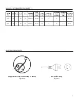
Pumps and floats equipped with a 3-prong 

grounded plug must be connected to a 

3-wire receptacle. Do not attach to exten-

sions or connectors without a 3-prong 

grounded plug. NOTE: Removing the plug 

from the power cord is not allowable per 

NEC code. Removing the plug will void 

the agency listing.

This pump has been evaluated 

for use with water only.

Risk of electric shock – this 

pump is  supplied with a ground-

ing conductor and grounding-type attach-

ment plug. To reduce the risk of electric 

shock, be certain that it is connected only 

to a properly grounded, grounding-type 

receptacle.

WARNING

CAUTION

Summary of Contents for STS21V

Page 1: ...Sump Pumps INSTALLATION OPERATION AND MAINTENANCE INSTRUCTIONS INSTRUCTION MANUAL IM236 ...

Page 2: ... code The pump must be connected to a dedicat ed electrical circuit protected by a prop erly sized circuit breaker or fuses Install a disconnect where required by code Code questions should be directed to your electrical inspector See Chart 1 for specific information Disconnect electrical power before install ing or servicing the pump The motor s automatic thermal overload protection may allow an ...

Page 3: ... never by the power cord Place the pump against the basin wall so the switch is to the center See Installation Data 3 PIPING 4 INSTALLATION IN SUMP 1 GENERAL INFORMATION 1 1 Sump pumps are designed to operate inter mittently and usually seasonally It is recom mended that you test the pump before your rainy season begins to insure that the pump and switch are operating properly 1 2 We suggest insta...

Page 4: ... debris children or pets falling into the basin See Basin Style in Section 2 3 6 SEASONAL SERVICE MAINTENANCE 6 1 If your sump pump only operates seasonally and then sits idle for months it is recom 5 OPERATION 6 SEASONAL SERVICE MAINTENANCE mended that you test the pump before your rainy season begins Fill the sump with water and check for debris and proper switch operation Remove any debris whic...

Page 5: ...ion Basin Solids Weight Style Diameter Size STS21V 0 25 1 60 115 2 5 amps Vertical 20 1 12 3 16 9 lbs STS31V 0 33 1 60 115 4 5 amps Vertical 20 1 12 3 16 9 lbs MODEL INFORMATION CHART 1 Suggested Pump Positioning in Sump Figure 1 Australian Plug Figure 2 INSTALLATION DATA INSTALLATION DATA MODEL INFORMATION CHART 1 ...

Page 6: ... General Pump Configuration Figure 4 Hose Adapter Figure 5 INSTALLATION DATA INSTALLATION DATA Typical Pump Installation in Sump Figure 3 PUMP ELECTRICAL PLUG CHECK VALVE FLOAT SWITCH UNION PUMPING RANGE ...

Page 7: ...7 NOTES NOTES ...

Page 8: ...for loss caused by interruption of service There are no warranties expressed or implied except such warranties as are definitely set forth herein The Company shall not be liable for damage or wear to pump caused by abnormal conditions failure to properly prime or to operate pump without flow or caused by corrosives abrasives or foreign objects No obligations other than those herein set forth shall...

Reviews: